
the classic multi-band ladder line-fed doublet…
© 2018 by KV5R. All Rights Reserved. Rev. 2/11/2019
Introduction
Cebik (W4RNL, SK) described a “doublet” as as a dipole that is fed with ladder-line and operated on several bands. So “multi-band ladder-line-fed doublet” is redundant, but I used it in the tag-line for search purposes. The general design formula for this type of antenna is quite simple:
- A wire dipole, center-fed, length (feet) ≥468/f, where f is the frequency in MHz of the lowest operating frequency. The length isn’t critical because we are not looking for resonance, as this this is a non-resonant antenna. And NO, an antenna does NOT need to be resonant to be efficient. Unless you feed it with coax.
- ladder line feed, with the length adjusted to place high voltage and current anti-nodes outside the ham bands.
- At the shack end, a 1:1 current balun/choke, designed for wide impedance range. And NO, not a 4:1 Guanella balun! Dropping the impedance by a factor of 4 also raises the current by a factor of 4, and makes things get hot, and heat is lost power.
- An antenna tuner. Yes, a balanced tuner is optimal, but with the right balun the typical unbalanced T-match tuner will work just fine, as long as the antenna side impedance is high, not low where T-tuners become very inefficient.
There are many books and articles about how to design antennas, but very few that actually show how to build them, so I thought I’d do this article about building, not designing, a big ol’ 80-meter doublet and feed line. Please note that my example is but one, and every antenna installation is different. This is just to give the reader a feel for how your big antenna day might go, and perhaps give you some ideas.
Planning & Preparation
A couple months after getting the AL-80B, I decided it was time to put up a better antenna. Back around 2002, I put up a 160-meter inverted vee, but a few years later one of its support trees died in a summer drought, so I took it down and rolled it up. Later, I put up an 80-meter dipole right behind the house, fed with about 30 feet of RG-8X, at about 20 feet, supported in the middle with the 20-meter vertical aluminum dipole (see elsewhere on this site). It worked okay, but not great. I mostly used it for occasional receiving during those years, when my 706 was crapped out and I didn’t have money to replace it.
After going QRO, I decided the existing one was too close to the house, and the RG-8X was just too lossy at 800 watts. Indeed, I burned up and shorted a PL-259 while trying to load the amp on one of the upper bands. (Yes, RG-8X will handle 1kW, but only if the SWR is low.) That’s when I decided it’s time for a proper, heavy-duty antenna, one like I always wanted to build. And besides, how can I write web articles about it unless I actually get out there and do it? 😉
My biggest problem was where to put it. You’d think that with 5.5 acres of trees, it would be simple, but not so! Getting a long antenna wire up past intermingled branches is almost impossible, unless you happen to have a helicopter handy. And I didn’t want it too close to the house, because that’s just asking for RFI problems. I finally located a 190-foot clear span down the path in the meadow, about 125 feet from the house, where I could put up a 130-foot dipole, about 35-40 feet high. And the ground is always wet down there (the water table is at the surface), so it should make a good reflector and not be too lossy.
Collecting the Materials
I ordered some insulators and RF connectors from MFJ, and a 500-foot roll of 3/16-inch UV-resistant Dacron (rated at 770 pounds), and a couple 50mm stainless steel pulleys from Amazon. Then I went to the lumber yard and purchased a couple 12-foot pressure-treated 4-by-4s. I then stopped at Tractor Supply and picked up some ½ by 8-inch monster-sized lag bolts, and some 3/16th cable clamps. The big lag bolts are long enough to not get buried in the trees as they grow for many years, and strong enough to take any foreseeable load. I used the little cable clamps on the #10 wire instead of tying knots or soldering splices, which makes the antenna easier to adjust, if needed.
I already had the wire, almost 500 feet of stranded #10 AWG THHN, and although #14 would have been sufficient (and much lighter), well, I had the #10 and decided to make good use of it. It was in two 250-foot pieces, as I had previously used it to feed a water pump down at the creek, and i decided to follow W7FG’s example (trueladderline.com) and make each half of the antenna and ladder-line out of continuous, un-spliced wire. In the past I have observed that stranded wire will eventually break at a solder joint, so I decided to use no solder on this antenna, except for the copper ring-lugs at the shack end.
For spreaders, I ordered a box of 200 Zareba Ribbed-Tube Insulators ($15), which are made for stapling high-tensile electric fence wires to wooden posts. I went to the electrical supply and purchased a bag of Thomas & Betts Ty-Raps™, the 11 by 1/8th-inch size, to run through the 4-inch ribbed-tube insulators. Notes: (1) Yes, Ladder-Snaps are probably better, but they are designed for #14 wire, and will not snap on #10; and (2) Yes, you can get 3/8ths black poly or PEX tubing, cut it into 4-inch pieces, and drill holes, or notch and hot-glue, or any way you want to do it. I just did what seemed easiest under the circumstances. I put a spreader every four feet. No, you don’t need one every 12-18 inches as some writers claim—that’s just silly. The impedance on the line is all over the place, so a little wig-wagging of the wires between spreaders won’t hurt a thing. However, where the line is slack, every two feet is better, lest it twist over on itself.
To get the support lines up, I spent all one afternoon with a wrist-rocket and a Zebco fishing reel, shooting a 2-oz fishing weight over branches, until I finally got the ones I wanted, then pulled up #36 nylon string, then pulled up the Dacron lines. At the near-end tree (a giant Sweetgum) I hit a big branch at about 40 feet, and that end will be tied fast, without a pulley. At the far end I got over a rather wispy oak at about 35 feet and pulled up a pulley with Dacron. With more Dacron looped through the pulley, I then pulled up the antenna (the next day), and tensioned it with a concrete cinder block.
Note that, with a high-power antenna, no part of the antenna or ladder-line may touch any foliage. Running insulated THHN wire through trees is fine at barefoot power, but never do so at high power, because at a voltage anti-node (several kV) the 600V THHN insulation will surely fail, and it may start a tree fire and probably burn the wire in-two as well.
Now let’s look at some pictures. Please excuse my photography; I was concentrating on getting this thing up and done, and did not plan my photos very well.
Antenna Day Photos
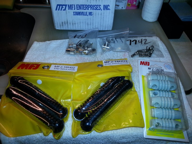
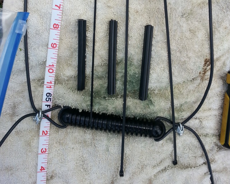
I thought I’d do it “right” and get some proper insulators, but you can also just cut some pieces of 3/4-inch PVC pipe and drill holes in the ends, which will work just fine.
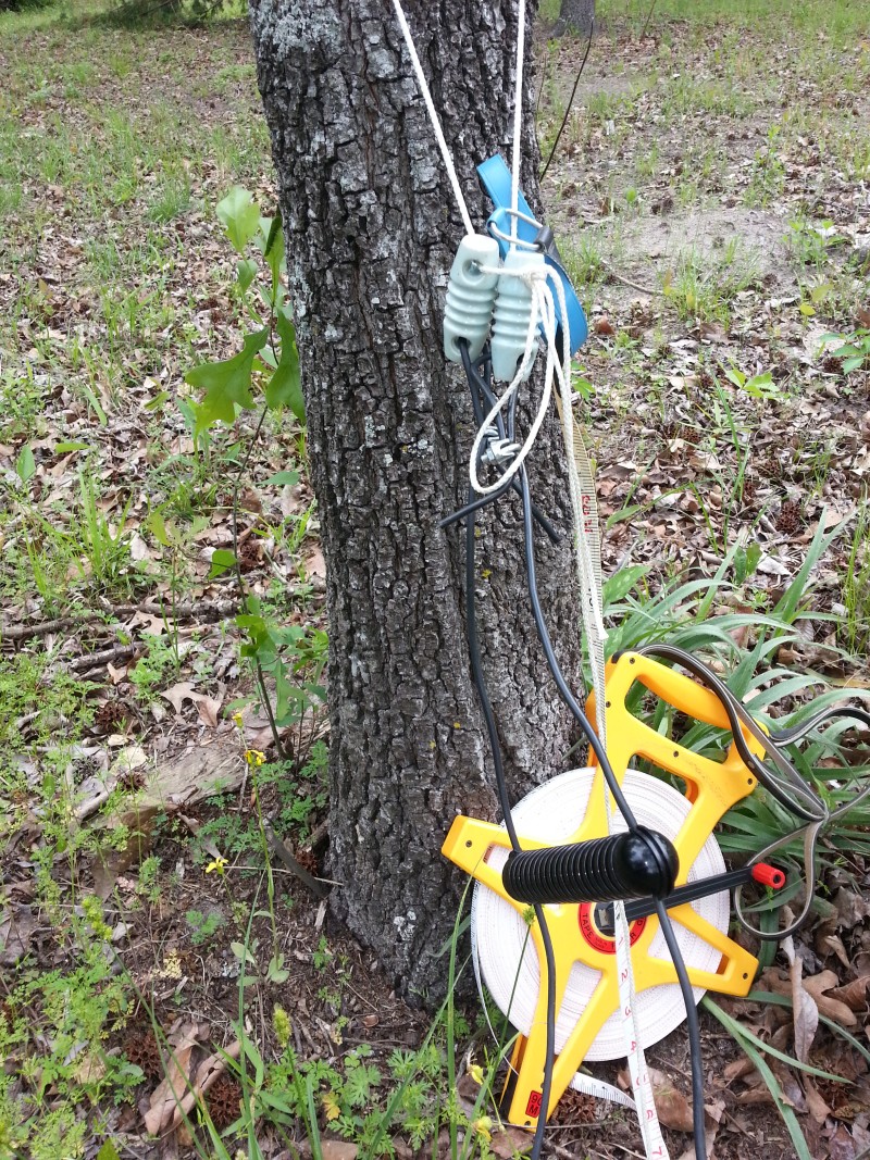
I laid out the two wires between two trees. Put the wires through the big center insulator, then put an end insulator on each wire, using cable clamps, and then tie then together around a tree. Note the 330-foot (100 meter) open reel tape measure ($17 at Harbor Freight). If you build wire antennas, you need one.
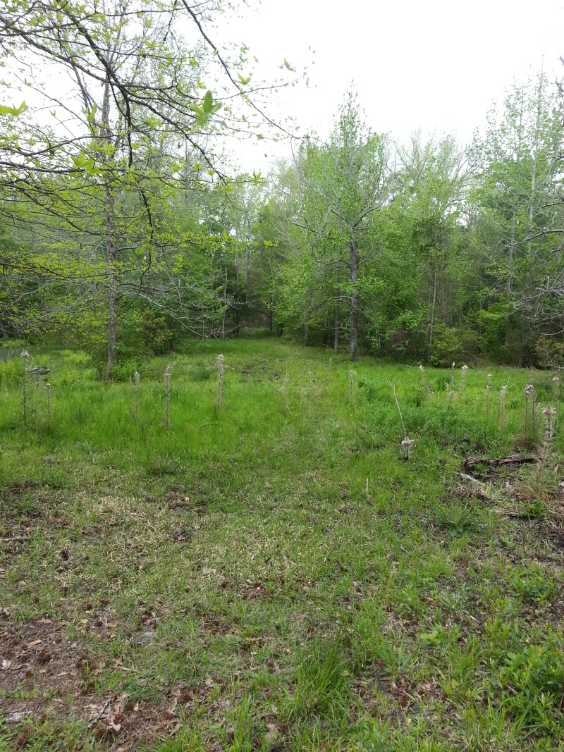
Looking down the path where the antenna will go.
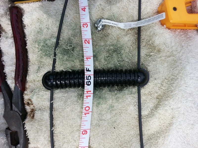
I stretched the wires and the tape measure down the path, and set the center insulator at 65 feet, for a 130-foot dipole.
Then clamped the wires here to establish the feed-point. No solder joints!

This is how I attached the ribbed-tube insulators as spreaders, using cable ties. Be sure to get the good ones, outdoor rated, with the stainless steel catch in them (T&B Ty-Rap™), and don’t even consider the cheap hardware store cable ties, as they will fail in short order.
I pulled the ladder-line section of the wires between two trees about 160 feet apart, and started adding spacers. I used a 4-foot fiberglass rod as a measure between spreaders. After all the spreaders are done, go back along the line and square up each spreader, then pull the cable ties very tight with pliers, then clip off the tails with wire cutters.

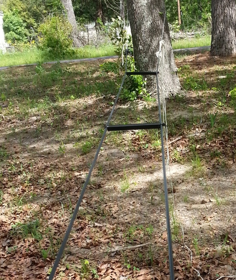
Support the line with a step ladder so you don’t have to bend over to add spreaders. Move the step ladder along as needed.
It took me about an hour and a half to put in all the spreaders.
At the other end the feed point was tied to another three. It’s very important to have exactly equal tension on the wires as you add spreaders. Before you start, adjust the support line you have around a tree until the wires hang at equal height in the center of the span.
Sorry, but I didn’t get any pictures while actually pulling up the antenna. My hands were full!
½x8-inch lag screws should hold up a heavy antenna for a long time. I would have used eye-screws but they didn’t have any that long. Another option would be the giant screws used for farm gate hinge pins. Don’t use nails, as they get buried in the tree after several years. You need something long enough to go through the bark and sapwood and well into the hardwood, with several more inches sticking out to allow for tree growth. Fifteen years ago I used 20d nails and they are now all buried, just waiting to destroy my chainsaw someday…
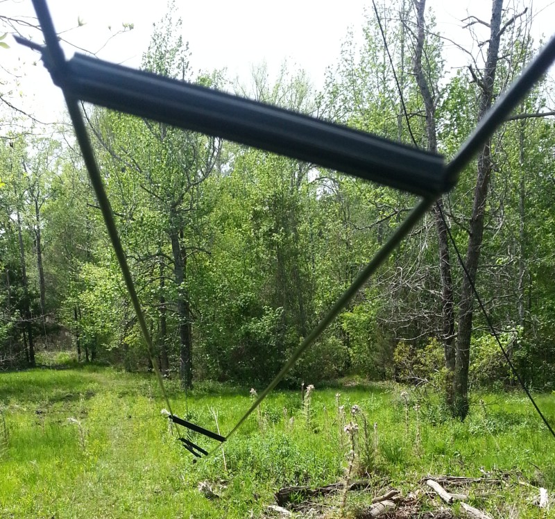
The far end of the antenna is supported by a pulley and counter-weight. The pulley line is tied off here.
The counter-weight. Note that if you have children around, this might look like an inviting swing, so you’ll want to put it up like 8 feet high. I found that pulling the antenna support line down, and the cinder block up, and tying a knot was a real chore. Plan your work accordingly. Maybe set the block on a step-ladder. I have lowered the antenna twice since then, but by untying the other end, not the cinder block. Be sure to leave plenty of coiled-up extra line on one end or the other, so you can let the antenna down when needed.
Do you really need a counterweight and pulley system? Yes! Dacron isn’t nylon, it doesn’t stretch, and the trees may sway in opposite directions. Also, if a giant tree falls across your antenna, it will just go all the way down to the ground, and the counterweight will go up, but nothing will break.
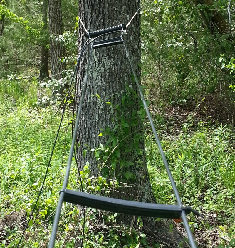
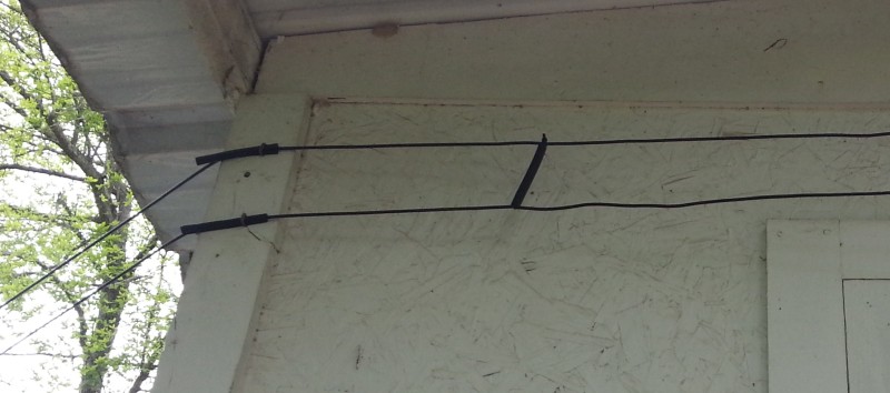
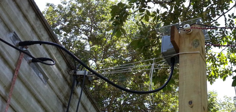
After planting a couple 4x4s in the ground, I routed the ladder-line as shown. Note that at each end of the span, the wires are NOT looped around the insulators on the poles, but are supported by solid wire, a couple feet long, wrapped around the ladder-lines.

At the pole under the feed point, notice the slack in the vertical portion of line, which I left so the antenna could bob around as the trees sway in a windy storm. I later added more spreaders to this slack section, so the line could not possibly twist over on itself when whipped around in the wind. If open-wire ladder-line gets twisted over, and you don’t notice it, it will probably blow right through the insulation and short out the next time you hit it with high power. Remember this is 600 volt insulation, not 6,000, so keep them apart, and away from branches. Notice that my spiraled support wires are attached to insulators, but the ladder-line is not.
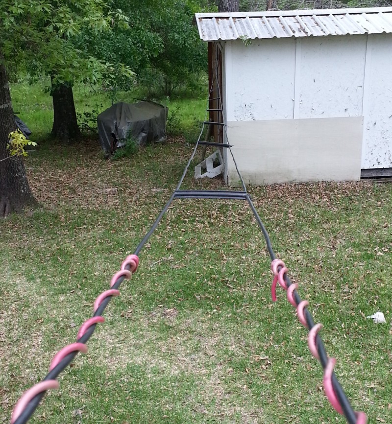
This storage building is in the way, but it provided another support. Yes, the line is almost too close to the metal roof, but any lower and the door would be blocked. I had planned to go around the other end of the building, but a Bay Laurel tree’s branches blocked that route, and since I’m very allergic to Laurel, I decided to not drag out the extension ladder and chainsaw, then spend the next month with a rash.
The second pole is planted about a foot from the house, just outside of where the tuner is located.
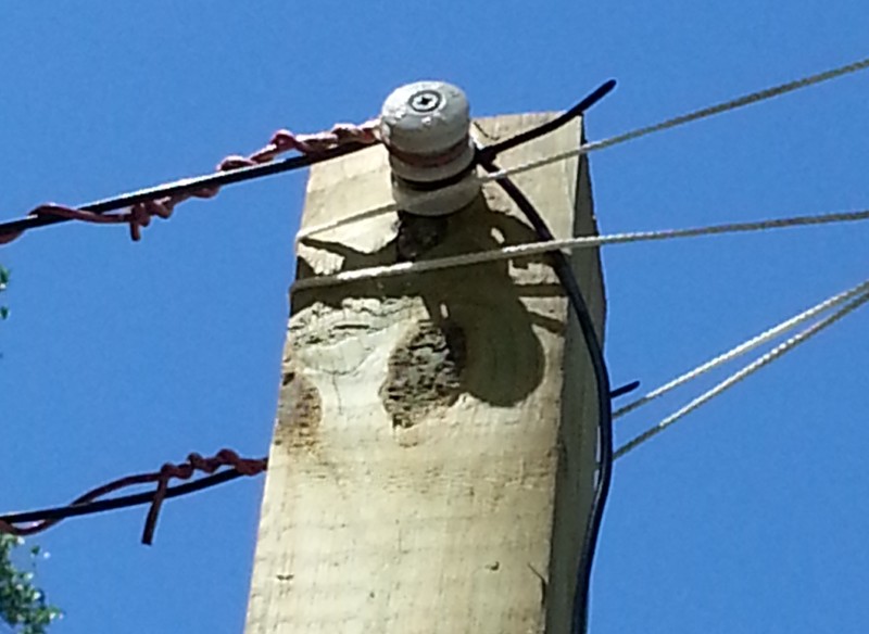
Post insulator and ladder-line suspension detail
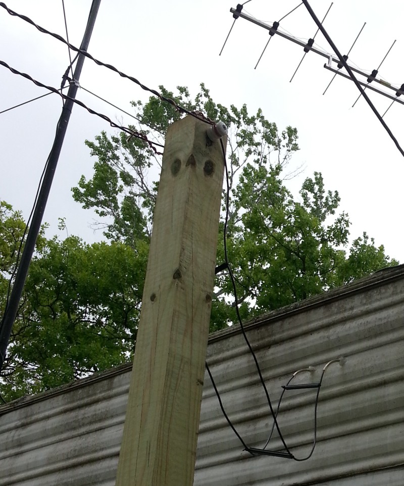
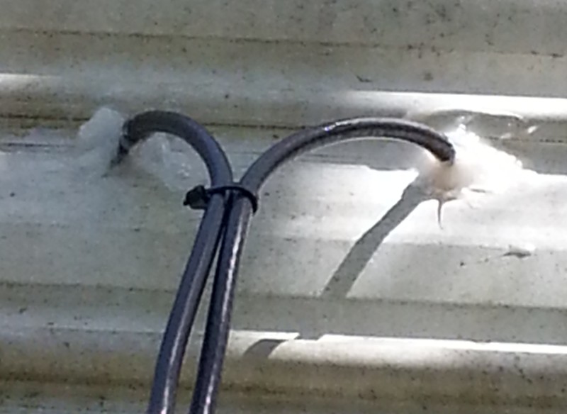
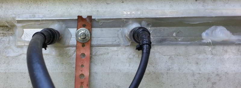
The line then just goes right through the wall…
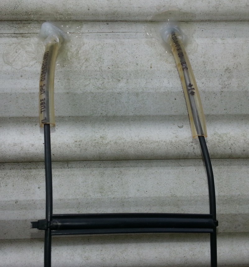
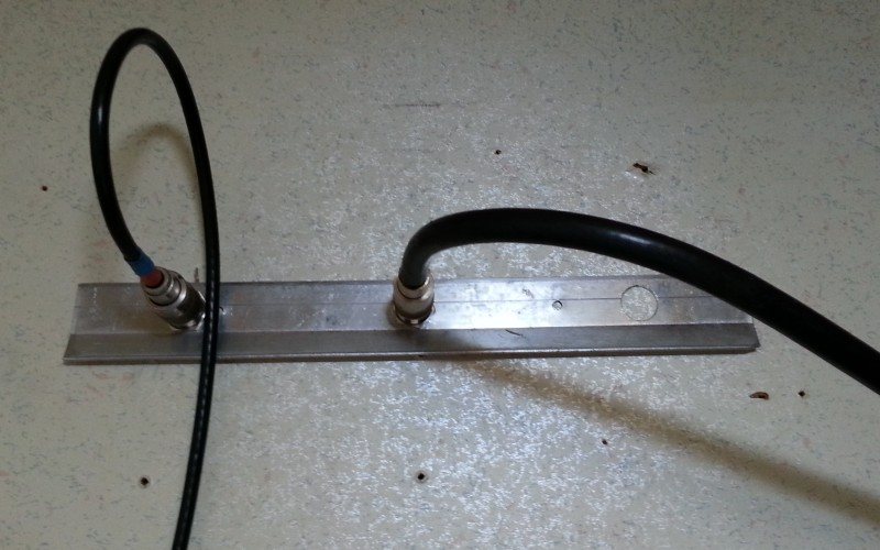
… where I used two pieces of 3/8ths-inch vinyl tubing as extra electrical insulation where the wires pass through the aluminum.

Inside, I crimped and soldered copper ring lugs, which connect to the feed-through insulators on the back of the 989D tuner.
Note that I made three different entrances. First, I came directly in as shown above. But I didn’t like the hassle of unscrewing wing-nuts on the back of the tuner to disconnect for storms, and there was no easy way to ground the leads. So I made a second entrance using twin coaxes, which are much easier to disconnect. Still later, I decided to purchase a Balun Designs 1171, an excellent 1:1 choke balun made just for ladder-line feeds. I put it out on the pole, and come in through a grounded 4-inch bulkhead fitting with RG-8 jumpers.
In case you’re wondering, all three entrance methods tuned up the same and worked fine, but the last one is much more convenient, and I recommend it. When thunder approaches, quickly unscrew the inside jumper from the bulkhead, which is grounded with its own strap and ground rod, and you’re safe (well, relatively safe).
When I switched the entrance to twin coaxes, I replaced the insulators in the 989D with SO-239 connectors. I had to slightly enlarge the holes.
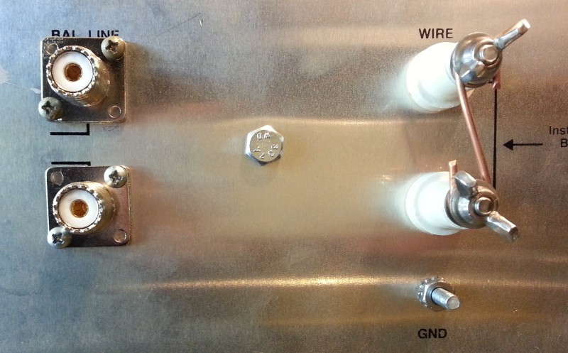
If you ever do this, don’t be tempted to run a regular differential-mode coax from here! These are meant to be used with twin-coax feed, where the two coax centers are in differential-mode, and the shields are tied together and grounded by the case of the tuner.
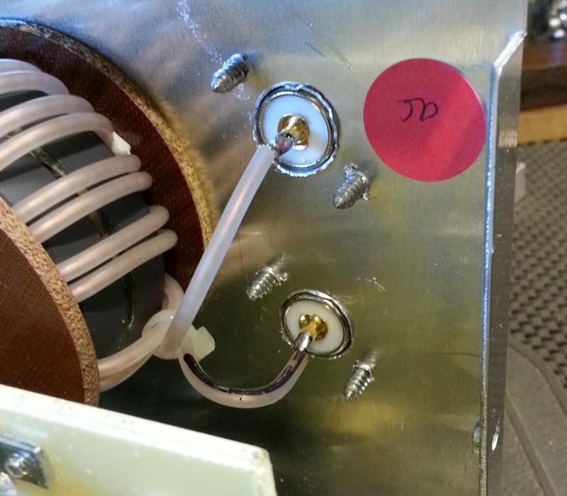
Inside detail
Where the short twin-coaxes attach to the ladder-line, insulate it well. Solder the shields together but do NOT ground them. You want them grounded only at the tuner end. Then waterproof the shields with a glob of silicone caulk to keep water from wicking into the coaxes.
The twin coaxes went in through the holes where the tubings were.
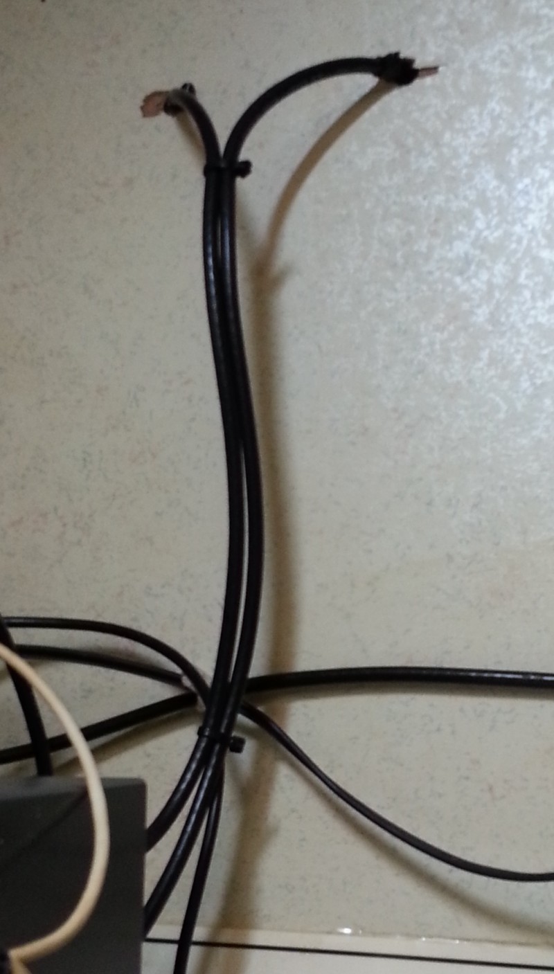
Note that you can bring twin coaxes together as a pair, at least for a very short distance. The shields provide electrostatic shielding, but not magnetic shielding. However, if the feed line is balanced the fields will cancel and all you’ll have here is a bump of lower impedance, which doesn’t hurt a thing.
After I received the 1171 balun, I completely re-did the feed entrance again. This method, with the balun outside, and short coax coming in through a grounded bulkhead fitting, is what I recommend. It has several advantages, including easy disconnection, and outside grounding.
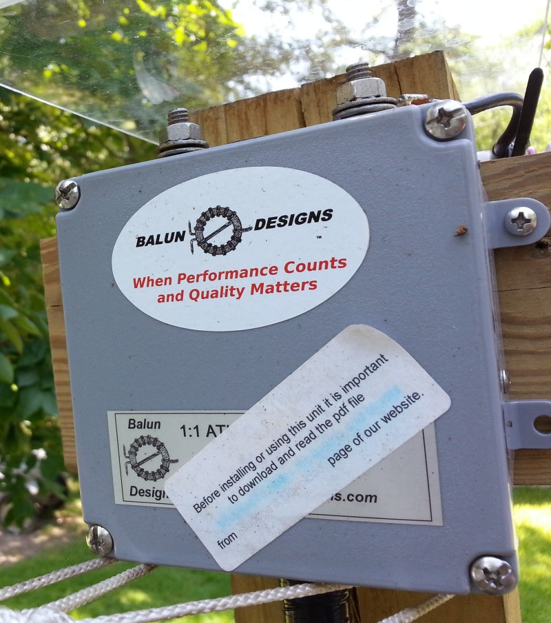
The Balun Designs 1171, mounted about 10 feet high on the 4x4 pole.
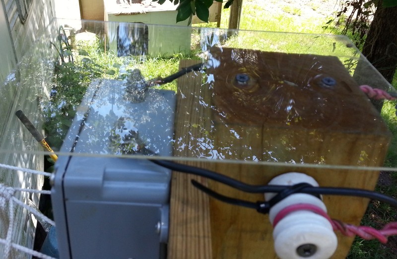
I had this Plexiglas scrap, so I used it as a rain shield, as I don’t have eaves. The 1171 is waterproof, but I don’t want water standing on top of it between the connections. If you order one, get it with the connections on the sides.
I ran a short jumper to the bulkhead.
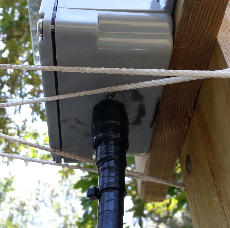
Any time you put a PL-259 outdoors, be sure to wrap it with at least two layers of half-lapped Scotch 33+ tape. Never use cheap vinyl tape, as it does not stretch and form well, and it comes undone after awhile and leaves a sticky mess! Scotch 33+ is the only way to go. You could also use Coax-Seal, but unless you put tape under it, it will be a big sticky mess when the day comes you have to undo that connector. Note the cable tie around the tail; keeps it from unfurling.
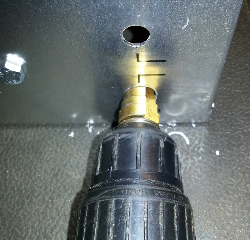
I had this scrap of aluminum, which was a carpet edge protector, so I cut two pieces and clamped them together and drilled holes with a stepped-bit. Then I mounted one outside the wall and drilled through the wall with the stepped-bit, then pushed the 4-inch bulkhead fittings through the wall and went inside and added the indoor piece.

The outside plate is grounded with 3/4-inch copper plumber’s strap to an 8-foot ground rod. Yes, 2 or even 4-inch copper flashing sheet would have been better, but oh my! $60 for a little 10-foot piece? No thanks. But do use copper strap for lightening grounds. Regular wire, even very large wire, is not good. It needs to have a large surface area to accommodate skin-effect that occurs at high voltage.
I will probably get some grounding guru telling me that all ground rods must be connected together with heavy cable. No thank you. This is my lightening impulse ground only, and I don’t want any of that pulse going through the house grounds or anything else. When I disconnect the coax inside, and unplug the power, the equipment is isolated, not grounded. This goes against much of the old advice, but many hams over the years have observed that most equipment damage from lightening impulses is via the ground path! And many who have lost equipment are now isolating, instead of grounding, during storms. Nothing is 100% fool-proof, but in my (and many others’) opinion, a grounded antenna, and isolated equipment, is the safest way to go during storms.
The indoor side of the bulkhead is easy to reach for disconnection of a 2-foot jumper that goes to the tuner. This is much easier than reaching around to the back of equipment.
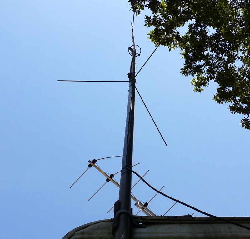
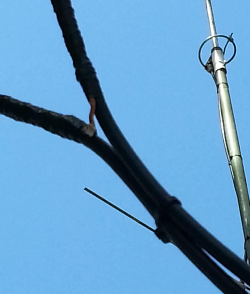
The smaller coax you see up there is from my Cushcraft ARX-2B, a 2-meter antenna. Yes, I used RG-8X for it, since it’s only about 15 feet long. It’s not very high, but will hit all the repeaters in the surrounding counties. The ARX-2B is a three-half-wave colinear design, with about 7dBi gain. I got it about 18 years ago for $49, and I see they are now $99…

Be sure to plan things so you can make large radius bends on your RG-8 jumpers. Use a 90-degree fitting if necessary to reduce the room needed behind equipment.
Performance and Tuning
The doublet performs as expected. It’s a large aperture, low-loss design, at a reasonable height, with a total system efficiency probably over 95%, not counting ground loss. The ground loss will be nowhere as good as one over salt-water, but it is over wet, acidic ground, as the water table is at the surface there.
On the higher bands, it will have multiple lobes and nulls, which are deeper at lower angles, so this type of antenna is never going to talk well in all directions on 20-meters and above. As for the elevation angle, the following image, by W4RNL, compares closely with the ones I modeled long ago in the NVIS article.
.gif)
For the 40-foot-high graphs, we see that on 80 the maximum angle of radiation is vertical (NVIS), although down only -3dB at 37 degrees. So for the regional five-state area around Texas, it will do very well. On 40, the vertical lobe begins to collapse, and the max power angle is about 50 degrees and the half-power points are at 22. This will cover most of North America when conditions are favorable on 40. At 20 meters, the height is such that the vertical lobe has collapsed into an inverted cone, and the max power is at 24 degrees, with half-power at 12. In the directions of major azimuth lobes, it will be a modest DX antenna. And at 10, a little power is wasted in high lobes, but most of the power is at 12 degrees.
So, does all that mean it is a great antenna on all bands? Certainly not. It’s a great regional antenna on 80 and 40, and mediocre on 20 and above. This antenna is for for the rag-chew crew, not DXers. But yes, it certainly will work some stations on the higher bands; it just will not compete with Yagis, or even good verticals, on the higher bands.
As for tuning, I was a little surprised to initially have problems tuning it on 10-meters, but a little adjusting of the ladder-line length, then the antenna length, moved that spot above 29 MHz, where I’ll never use it. Before the adjustments, the SWR was flat across 20 meters, without a tuner! The ladder-line just happened to be the right length to transform it to 50 ohms on 20-meters. Strange things do indeed happen when you run high SWR on a feed line and it acts as a transformer.
As for efficiency, nothing gets warm enough to detect on any band. Both the tuner and the balun remain cool at 1kW, and a lack of heat is a good indicator of high efficiency. Of course, much would be lost as dielectric heating in coax, which is distributed along the line and not easily detectable, but with ladder-line there is no dielectric to heat, so power gets to the antenna regardless of the high SWR on the line. So with ladder-line the only things left to get hot is the balun and tuner, and if they don’t, then things are working as they should. Of course, with the wrong length of ladder-line, at some frequency, a current or voltage anti-node may land right on the balun and/or tuner, and cause problems, either excess voltage (arcing), or excess current (overheating), so if either condition exists, the solution is to change the length of the system and move the offending anti-node out of the ham band. And NO, bigger baluns won’s fix it; better grounds won’t fix it; nothing will fix but moving it away to a frequency you don’t use.
Conclusion
I hope this article has given you some ideas on how to put up a big doublet. Make a plan, collect all your materials, then execute your plan.
What would I do differently? If I didn’t already have the wire, I’d order about 600 feet of #12 copper-clad aluminum (CCA) wire, for about $45 on Amazon. It’s much lighter, and much lower cost, and will perform about the same as pure copper wire. But isn’t aluminum four times the resistance of copper? Yes, at DC, but at RF, due to skin effect, most of the current runs in the copper coating, so the resistance is virtually the same as pure copper wire. This much lighter wire would also mean smaller support lines and hardware, a flatter flat-top, and easier handling. It would cost significantly less, and work just as well.
I would also design both the ladder-line and antenna length so that it presents close to 500 Ohms of impedance at the tuner on several bands, if possible, because T-tuners are most efficient with around 500 Ohms on the antenna side, and also 4-inch ladder-line has a characteristic (matched load) impedance of about 500 Ohms. In other words, design the whole system to hover around 500 Ohms, then let the tuner take it to 50 for the radio, which it will do at around 95-96% efficiency. This would mean that both the peak current points (odd half-waves), and peak voltage points (even half-waves) would need to be positioned between the ham bands, so the 500-Ohm feed line would never see either very high, or very low, feed-point impedances within the ham bands. After I get caught up with all this web writing (I’m years behind) I need to do some modeling to see if this idea is even possible, and if so, what the numbers might be.
What’s Next?
That pretty much wraps up what I did in ham radio in 2018. In late 2018 and early 2019, I decided to get deeper into the electronics hobby, and I assembled a nice test bench, something I’ve wanted to do for decades.
73, — KV5R
In your last comments you say that you would use #12 copper-clad aluminum (CCA) wire. Would that be solid or stranded CCA?
Great articles, thank you.
Kelly – NM7H
The stuff they sell on Amazon is fine-stranded (69 I think) “primary wire” generally used for low-voltage, like trailer wiring, etc.
I’ve since heard that wire’s copper is extremely thin, and connections corrode very fast. Make sure connections are completely waterproofed with liquid electrical tape, silicone caulk, etc.
73, –kv5r
Hi Harold!, I am quite impressed by volume of interesting practical info I have seen about open lines in your site, and I have also learned a lot reading the questions and answers. Reading your answer to a question I have
thought I could solve my problem mounting an antenna for 40 m and up with 2 X 31′ arms and using 2 X RG6 as pararell line with a lenght or 3/8 lamda in 40 m, do you think it could be OK? I have no space for a longer wire antenna at my roof, and I will have to mount it as inverted V with the apex at 22′ high, so I think it won’t be a DX antenna in 40, but in higher bands who knows?
Thanks a lot beforehand for your attention…
Fito
EA7AQV
Yes, that should work fairly well. On 40 it’ll be high-angle, on 20-10 lower angle but with lobes and nulls. Let us know how well it works!
A better DX antenna for 20-10 for your small space would be the “Cobweb” antenna; they are omni-directional and do pretty well on DX. 9 feet square on a 30 foot mast.
73, –kn5r
Yes Harold, I have thougt about the Cobweb, but I am limited not only in horizontal space, also in heigth (no more than 22′). May be at last I will try an Inverted L of 3/8 lamda in 40m against 4 1/8 lamda radials; with a remote antenna tuner may be it could work.
I will keep you informed.
Thank you very much, and Merry Christmas.
Planning on putting up a 55′ each side inverted ‘V’ at 30′ fed with parrallel rg6 wiyh grounds tied togeter amd each side of the ‘v’ tied to one of the rg6 center conductors. i use a MFJ-993B and a 7300.
Ideas and comments?
Yes that should work fine. I’d run the legs out to ~62 feet though, if possible. Regular ladder line would be a little better than twin coaxes.
Tie shields together at both ends but ground them at tuner end only.
73, –kv5r
Hi Stanley…I’ve been feeding my doublet for many years with about 20 feet of open wire (4″ spaced) and then about 15 feet of parallel coax (quality RG? 75 ohm type). Braids are joined at both ends but only grounded at the balanced matcher. Seems to work well but can’t remember where I read about that idea and find little reference anywhere about using “balanced co-ax). Any comments?
Just to add, not easy to run open wire in to shack.
73 Mike G4IIA
Just want to be sure I understand.
The outside bulkhead is grounded. And the coax shield is connected to the grounded bulkhead through the fitting on the end of the coax.
Yes. So, one side of the antenna is DC grounded. But not RF grounded, because of the choke/balun.
hi the only trees i have to use are only far enough apart for 40 meter dipole when i can afford a sturdy enough pole i can build the 80 meter or even a 160 meter dipole,i’m using 600 ohm ladder with a ldg-600 tuner, is the 1:1 balun ok and is 32 to 34 of ladder line a good start thanks tom i originally i thought i could make the 80 meter dipole fit
No, 32-34 is close to a quarter-wave (on 40 meters) so would be a length to avoid on a 40-meter doublet. It would transform the low impedance at the feed-point to a very high impedance at the tuner.
It is, however, a good length on an 80-meter doublet, as is 96 feet.
Remember – desirable lengths are odd-eighths of the antenna’s fundamental. Exact length is not important, just avoid getting close to quarters and halfs.
what if your ladder line is only 25 30 ft to the balun/auto tuner my shack is right nex to the center of the dipole
thanks tom wb6nfu
Should be okay; for an 80 meter dipole I’d shoot for 32-34 feet of ladder line (1/8th-wave on 80); this will form a quarter-wave impedance inverter on 40 to bring down the very high impedance on 40 where the antenna is 2 half-waves fed at the voltage antinode.
The general rule for “good” ladder line lengths is odd-eighth-wave, i.e., 123/f=feet, x1,3,5,7,9 etc. (where f is MHz of the antenna’s fundamental resonance).
Even then, some pruning may be needed to fix a band that won’t tune; this is usually 10 meters, where a couple feet will make a big difference, if needed.
73, –kv5r
I like resonant antennas because it’s possible to match the coax transmission line to the antenna radiation resistance using a custom wound toroidal transformer (balun) at the antenna feedpoint. Since the radiation resistance is unique to each installation, it can take some trial and error with the transformer turns ratio to get the best match. When properly matched the coax is not very lossy. I find coax easier to handle, route, and maintain than ladder line. This setup is limited to a single band, and may not be desirable to some stations for that reason.
Indeed, a resonant dipole with coax is best, and simplest, for narrow band operation. The radiation resistance of a resonant dipole is usually well within in the range of 25-100 ohms, which does not present an SWR on the coax high enough to incur any noticeable loss.
The main concern of such an antenna is decoupling the outside of the shield with some form of choke at the feedpoint.
The downside of the resonant dipole is its very limited bandwidth, particularly on 80 meters, which is why many people are using the style depicted in this article.
73, –kv5r
WOW you do have a lot of trees!!!
Hmm me thinks a few could be eliminated.
Yes, I live in the woods 🙂 I’d gladly eliminate a few hundred trees if I were able! Cutting them down is easy, but cutting them up and heaving tons of wood & branches into huge piles is way beyond my ability. Too old & tired! And hiring it done is way too expensive…
Wish I was closer would be happy to help out. I have cut down many a tree for fire wood when we lived on the farm.
Good exercise and loved the smell of the wood.
Thank you for your reply.
What I am concerned of is that the doublet will be installed at about 20′ from the rooftop of the 7-floor block where I live, in a noisy big city (I cannot mount it higher).
I am mainly interested in dx’ing.
Do you think I can get better results with respect to the multiband rabbit-ear (rigid V-dipole) I currently use?
73 Marco IU8HXM
Yes it will be better than your much smaller rigid v-dipole, mainly on the low bands 80-40. On higher bands it will have deep nulls in several directions.
If your main interest is DX, the 80 meter doublet is not a good DX antenna. You should consider a multi-band vertical on that 7th floor roof, if roof is large enough to lay out several quarter-wave radials. Another good choice might be the Cobweb antenna, which is small, horizontal, omni-directional, without nulls.
A vertical or Cobweb at that height will have a very low elevation angle and be good for DX. Of course, a yagi or hex-beam would be even better, though much more expensive.
73, –KV5R
Hi Harold,
I would like to build an 80-meter doublet to be used from 80m to 10m.
The ladder line will be about 110′ long.
As a first try, I would like to connect the ladder line directly to the balanced input of my MFJ-993B ATU, which is equipped with a 4:1 current balun. Do you think there are any risks of arcs or heat? Do you think this is a lossy setup?
If results are not satisfactory, I will put a 1:1 balun outside the window and I will use 10′ of coax to connect the ATU. Given that there will be losses in the coax, is this solution better than the former one?
73 Marco IU8HXM
Hi Marco,
That will probably work fine either way.
Years ago I ran a 160 meter doublet with window line to a 1:1 bifilar choke & 15 feet RG-8 to an MFJ-993. It worked well & tuned on all bands. Then I brought the ladder line all the way in to the 993 and used its internal balun, and it seemed to work just a little bit better.
So whether to use the internal balun or an external one comes down to more of a matter of entry convenience & disconnecting for lightening storms.
At 100 watts there are no risks of arcs or overheating in the MFJ-993B because its software limits its tuning range when it detects extreme impedances. It limits further if power is in the 100-300 watt range. So it protects its components.
73, –KV5R
Harold-
Thanks for your advice with Marco’s question. Mine was identical; 80 M Doublet with home-made 600 ohm feed line fed to a MFJ-993b. Helps to see the questions and answers!
Matt
KB9YOJ