how to calibrate the Icom IC-7100 — ±0.1Hz is golden… 🙂
Copyright © 2018 by KV5R. All Rights Reserved. Rev. 09/13/19
As a former industrial instrument technician, I learned all about calibration procedures, and calibrated many things. I like things to be calibrated to the best possible precision, which is called the limits of resolution (of both the device and the calibrator), directly referenced (or traceable) to an official standard.
It’s amazing how many hams have never calibrated their radios. Back in the good ol’ days, calibrating radios typically involved a “complete alignment” procedure, where an expert technician with the right equipment and service manuals would align everything in the radio. Later, in the 80s, some radios had a calibrate knob that allowed the user to zero-beat the radio to WWV’s carrier. But you can’t actually beat at 0 Hz, because you can’t hear it, so an offset was used, and you still needed a frequency counter to measure the tone. But that has all changed now. Gone are the days of having to be satisfied with being a few cycles off frequency.
The IC-7100 (and other recent Icom radios) have a nifty REF Adjust in the Functions menu, where you can easily set the master oscillator to within about ±0.1Hz (referenced to WWV), and since the radio has a TCXO, it stays pretty close to that. The REF Adjust screen displays a scale of 0-100, but the resolution is actually 1 encoder pulse of the main tuning dial, or 1 press of the + and - buttons on the REF Adjust screen. There appears to be about 2.5 pulses per scale number, and each pulse will change the frequency by about 0.33 Hz (at 10MHz; it varies with frequency).
Does it really matter? Well, a few cycles off may be okay for SSB voice, but causes problems when running computer sound-card digital modes, where both frequency and timing are very important to the success and enjoyment of that aspect of the hobby. Calibrating your radio directly against WWV removes any additional error, since NIST/WWV is the defining standard.
In the following procedures, we will use a computer and digi-mode software to calibrate the sound-card device against WWV’s time ticks, then use that as an audio frequency counter to calibrate the radio’s display frequency against WWV’s carrier. So all you need is the radio, and a computer and software that will accurately count audio frequency.
Soundcard Software Calibration
All sound-card chips run a crystal oscillator, which establishes data sample rates, and they are all of rather low quality. The better digi-mode softwares provide a way to correct the sound-card’s sample rates by determining and then applying a correction factor, usually in parts per million (PPM). Having a calibrated sound-card is very important in determining exact audio frequencies and shift timings in the various digital modes.
Note that we are not actually calibrating the sound-card oscillator, just applying a correction factor in the software. This needs to be done for every digi-mode software that you use.
The most visually obvious sound-card clock error is seen in SSTV, where the received pictures are slanted. But until you calibrate your sound-card clock, you don’t know if it’s you or the other guy that’s off! Also, the very narrow digi modes like FT-8 and WSPR need a very precisely calibrated sound-card and radio. Some digi modes have AFC and can compensate a few cycles, but others do not.
After the radio is connected to the computer and audio levels are properly set, consult your digi-mode software’s Help and look for sound-card calibration. MixW and fldigi use the best calibration method: an SSTV-like picture is scanned with 60 LPM sweeps while tuned to WWV. The WWV clock ticks will eventually paint a vertical line, and if it slants left or right, your sound-card calibration is off. The longer you let it run, the better the accuracy, but 15 minutes or so is sufficient.
Using MixW or FLDigi to Calibrate the Soundcard
The MixW package contains a utility called CheckSR.exe, a free utility that is widely available on the web (search for it by name). You don’t need to get the whole MixW package to use CheckSR. It’s just a single file that you download and run. It displays a dialog box where you set your sound-card’s native sample rate, then start it and let it run for 5-10 minutes. After the numbers stabilize (the 1s digit), put those PPM numbers in your digi-mode software’s sound-card configuration panel. This will get you very close.
Next, to test and fine-tune the calibration, use the software’s WWV calibration feature.
In MixW, menu to Hardware, Sound Device Settings, and see the Clock Adjustment PPM fields. If you click Calibrate, it will say that you should switch to SSTV mode, WWV, and follow the instructions in Help. Do so.
In FLDigi,
- Menu to Configure, Soundcard, Settings tab. Set the Sample Rate for both Capture and Playback to Native (which will be 44100 for the 7100’s internal sound-card chip). Under that are Corrections fields where you will enter ±PPM values as needed. Leave the configure dialog open.
- Switch fldigi to WWV mode (OpMode menu). On the waterfall, set the detector line to 1000 Hz.
- Open the Floating Scope (View menu). Maximize the Scope window.
- Tune the 7100 to WWV (clearest frequency heard), and set mode to AM. It’s usually better to use 15 or 20 MHz in the middle of the afternoon, as the lower frequencies at nigh will have more doppler phase noise from changes in the path length. Also, night signals on 2.5 and 5 will have storm static.
- Switch to the Floating Scope window and observe that the tick sounds at 1000Hz are slowly painting a vertical line. Click on the edge of the line and it will shift it to the red center-line in the Scope. Let it run a few minutes.
- If the line is slanted, go to the Configure Soundcard Settings and change the RX PPM a bit, then let it run a few more minutes. Which way? If the line is moving left, the PPM is too high. How far? You can set it at +100 then -100 and let it run a few minutes and see the effect, then estimate where the center might be.
- Repeat until there’s no slant.
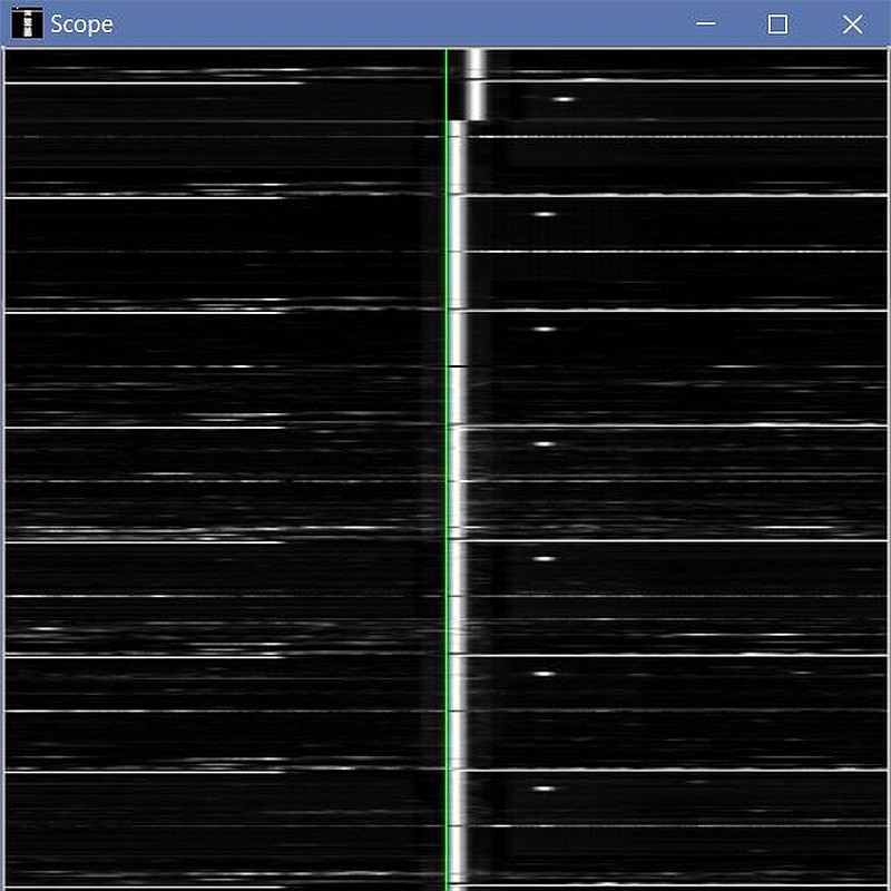
After several tries, I obtained this perfect result, with -16PPM in the RX field.
But What About TX PPM Setting?
Running CheckSR.exe, I observed that the Playback PPM error is always about one-half the Capture setting, so I initially set mine to -8, since RX was -16. But I wanted to fine-tune it, so I did as shown below.
Gettng it more accurate may be done with two radios and computers. Fldigi in WWV mode will transmit 1-second ticks similar to WWV. This may be received on another system that has been RX calibrated to WWV.
Or, simply run two instances of fldigi on the same computer:
- Set up radio: Set RF Power to minimum, set Monitor on, timeout timer off, and connect dummy load.
- Set fldigi to WWV and click T/R to begin transmitting beeps.
- Start a second instance of fldigi, set it to WWV, and open its Floating Scope.
- Run them for 15 minutes and adjust the transmitting fldigi’s TX pps if needed to correct any slant on the RX instance.
This will loop the beeps through the radio’s sound-card chip and compare the output sample rate to the input sample rate. I ended up setting the TX ppm the same as the RX ppm and did not get any slant. I did get slant when I set the TX -100, just to make sure it was really measuring as expected.
IC-7100 Calibration
Now that the sound-card is calibrated to WWV, we can use it as an accurate audio frequency counter to measure beat frequencies and calibrate the radio’s REFerence oscillator.
Set radio to exactly 5, 10, 15, or 20 MHz. Use the one with the clearest signal. Switch to CW mode, and if it changes by 600, put it back on zeros. Press the Speed/Pitch button and set your CW Pitch to 600 Hz. Switch back and forth between CW and CW-R. The 7100 will shift up or down exactly 600 Hz (above and below the display frequency) and produce a 600 Hz audio beat with WWV’s carrier. Go to Set → Functions → REF Adjust and carefully adjust it (with +- buttons, not the dial) until the audio beat is as close to 600 as possible. Read the audio frequency on the computer.
In MixW, set PSK31 mode, AFC On. Set the detector line on the waterfall to 600. Let the AFC zero in on it and read the audio frequency in the status line (0.1Hz resolution). Adjust REF Adjust +- until the AFC reads 599.9-600.0 in both CW and CW-R.
In FLDigi, menu OpMode, FreqAnalysis. Set the detector line on the waterfall at exactly 600Hz. Open the Floating Scope. In Analysis mode, the scope simply displays 3 lines. The center line frequency is where you have the detector line set, and the upper and lower yellow lines are ±2Hz. On the radio, switch between CW and CW-R, and adjust REF Adjust +- until the signal line is just above and below the center reference line on the Scope.
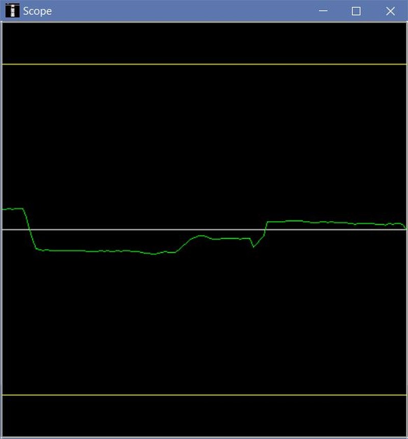
In fldigi’s Floating Scope window, you can see where I switched between CW and CW-R, and then adjusted REF Adjust on the radio, to get within about 0.1 Hz. If you want to see exact values, fldigi logs a file at fldigi.files/temp/analysis.csv.
In WSJT-x, use the FreqCal mode. It will tune the radio to 9998.5 kHz USB-D, then measure the beat at 1500 Hz.
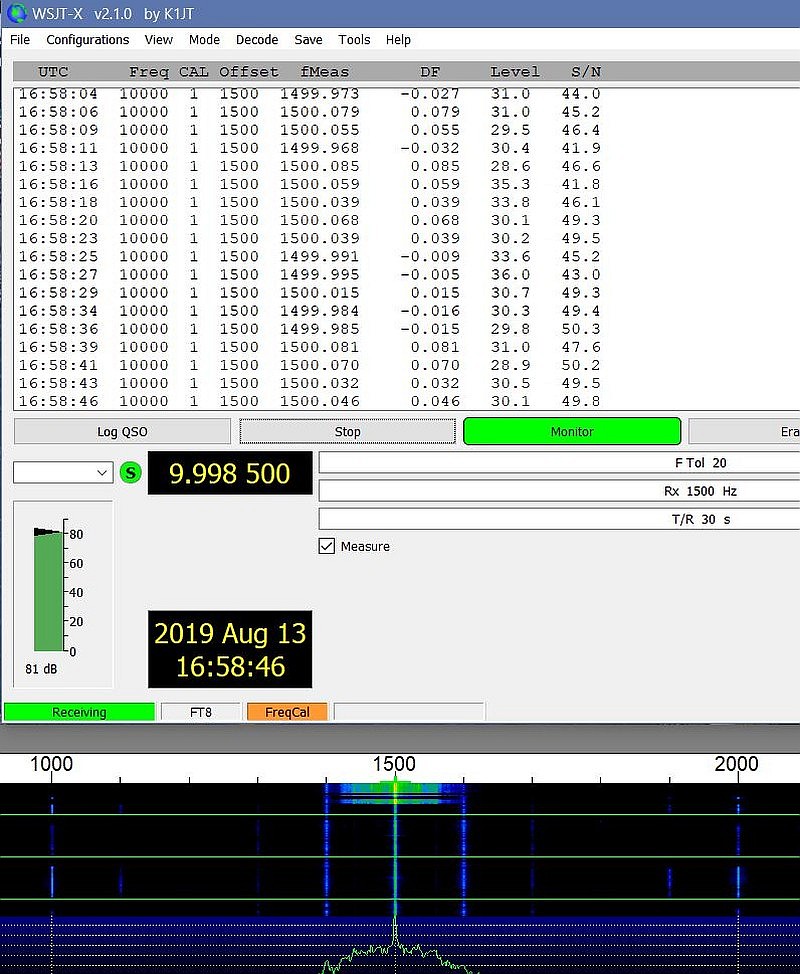
Notice the DF column: the resolution is 0.001 Hz! Note also my calibration accuracy 🙂 (The fluctuations caused by path length variations.)
Zeitnitz Soundcard Scope:
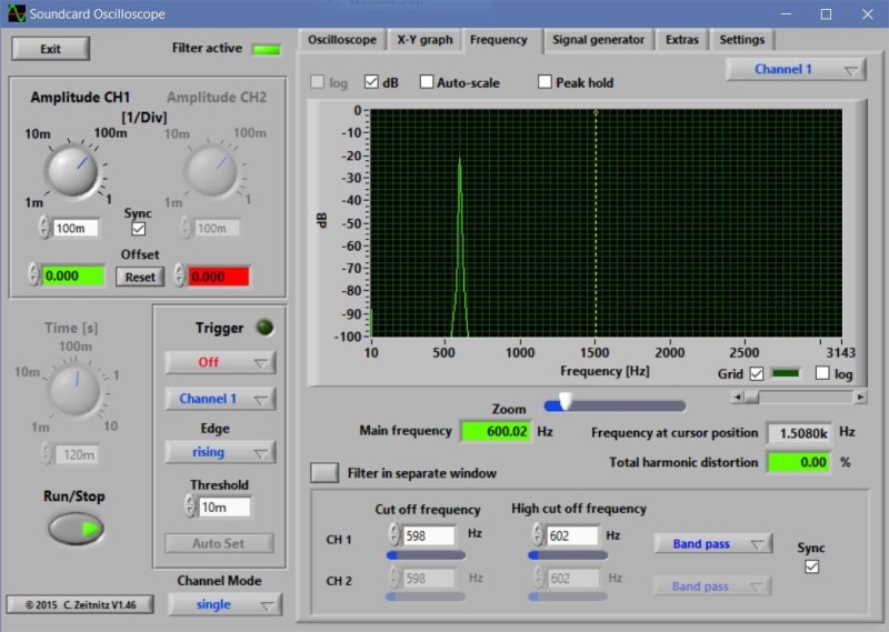
In Settings, set the input to the radio’s USB audio, then set averaging time to 10 seconds, then in the Spectrum tab set the filters for channel 1 to 598 and 602. Set the radio’s filter to 50 Hz. As above, use CW and CW-R and compare the offsets. The advantage to this one is that you can set the averaging time to 10 seconds and average out the path length fluctuations. Resolution is 0.01, as seen in the green Main Frequency field.
Quick Verify, as Needed
Soundcard: simply go to WWV, AM, and read MixW’s PSK31 AFC, or fldigi’s Analysis Scope, on the 500 or 600 Hz modulated audio tones (they are also reference standards, just like the RF carrier frequency).
Radio: simply go to WWV, CW/CW-R, and read MixW’s AFC, or fldigi’s Analysis Scope, on the 600 Hz CW offset beat tone.
Long-term Drift
When new, my 7100 calibrated at 42% on the REF Adjust scale. After a year of crystal aging, it ran 45%, and after two years ran at 48%. All crystals drift with age, so it’s a good idea to recalibrate every few months.
Alternates for accurate audio frequency readings
Windows: Soundcard Scope, by C. Zeitnitz (free). There are also some musical instrument tuner software that may work.
Linux: See the baudline site for info and Linux software.
If you are not connected to a computer that will read the audio frequency, just adjust REF Adjust until the CW/CW-R tones sound equal. You can also beat the 600Hz offset against the 600Hz tone that WWV plays on most alternate minutes, which will produce that WAAOOWAAOOWAAOO beat sound. This will allow you to get within a cycle or so by ear. If you have an audio oscilloscope, you can observe the beat between the 600Hz offset and the 600Hz modulated tone, and get it even closer.
Notes:
- When you are “calibrating” the USB Audio Device, you are measuring the the actual sample rates of the IC-7100’s internal USB Sound chip, not the computer’s sound card.
- The correction factor (usually in PPM) is stored in your digital mode software, not the radio. Nothing about the radio’s USB sound device can be changed except picking a sample rate, bit rate, mono/stereo modes. So you’re actually calibrating the software’s correction factor, not the radio’s sound-card.
- I think it is correct to say that you should always calibrate a soundcard at its “native” sample rate, which for the 7100 will be 44100. Calibration factors will be slightly different for different sample rates, so consult the Soundcard Calibration section of your digi-mode software’s Help documentation.
- DM780’s internal sound-card calibration app looks nice but it takes many hours to stabilize. It does not use WWV but uses the computer’s clock, which it updates on-line via NNTP every 5 minutes. Also, DM780 stores correction at actual calculated sample rate, such as 7.9983 kHz, not ppm like others, so it’s hard to calculate its setting to use in other programs.
What’s Next?
Adding an I.F. output and an SDR panadapter to the 7100!