how to connect an SDR to the IC-7100…
© 2018-2020 by KV5R. All Rights Reserved. Rev. 1/2/2020.
2020 Update
In December of 2019 I added an RF output to the 7100 and connected it to an SDRplay RSP1A. I have updated this article to cover both IF and RF taps. If you will use an RTL-SDR dongle (doesn’t receive below 25 MHz), you need the IF tap. If you will use a full-range SDR (or a dongle with a down-converter) you will use the RF tap. Both are described below. I’ve also added brief sections on SDR hardware and software.
Contents
Introduction
The Icom IC-7100 is a nifty radio. Like the old 706MkIIG, it covers all amateur bands (except 220) from 160 meters through 70 centimeters, in all modes. It’s small, and has a detached control head. But that’s where the similarity ends. The 7100 adds DStar digital voice, IF DSP filters (3 per mode, each tunable from 50Hz to 3.6kHz CW/SSB, to 10kHz AM, and to 15kHz FM), a DATA mode that used with SSB provides another set of three filter bandwidths for computer digital modes, and a built-in USB sound-card and serial interface. It connects directly to a computer with the supplied USB cable, providing USB audio, CI-V CAT control (virtual RS-232 serial via USB). In other words, it needs no interface box — it’s built-in! It also has an intuitive touch-screen and plain-text menus.
But unfortunately it doesn’t have is a real-time spectrum display, or an output for a panadapter. Of course, I just had to add one, because a panadapter is just too useful to be without. Gone are the days of slowing dialing through the bands to hear what’s there. With a panadapter, you see the whole band at once, and just click on interesting signals to instantly tune to them. Dialing through a band is like living in a house with one small window. Running a panadapter is like knocking out a whole wall!
What’s a Panadapter?
A panadapter is a spectrum scope. It displays a section of radio frequency spectrum as a real-time graph of signal strength (Y) and frequency (X). It also displays a recent history of signals as a moving “waterfall” graphic. This allows the user to see the whole band at once, as opposed to having to slowly tune through a band to find signals. It also allows the user to visually check the spectral purity of signals. So it’s like a spectrum analyzer, but thousands of dollars cheaper.
Many hams still do not understand the benefit of a panadapter. But once they start using one they see how useful it is and how much it adds to the enjoyment of ham radio. You instantly see band activity, adjacent QSOs, who’s splattering, and when another favorite frequency becomes active. You are no longer limited to that 3kHz window for band information. And after a little while, you’ll love tuning by simply clicking on a signal.
How it Works
There are several ways to implement a panadapter with a ham radio. Each has advantages and disadvantages.
External Antenna Switch
One way is to connect an HF-capable SDR (software-defined radio) to the station’s antenna, using the receive antenna loop on many radios, or an external automatic transmit/receive (T/R) switch. In this implementation, the SDR may be used as both a panadapter and a second receiver. The disadvantage to this method is that SDRs that will receive HF, and filter it properly, are rather expensive, starting at around $120. And there is always the possibility of blowing the SDR when transmitting, if switching doesn’t work just right. MFJ makes an automatic antenna switch for SDRs, for a mere $119.99… Ridiculous!
1st IF Tap
Another way to implement a panadapter is to have the SDR connected to the first IF (intermediate frequency) mixer of the radio, before the buffer amp and roofing filter. This method has several advantages: (1) no antenna switching is needed; (2) the radio’s front-end and band-pass filters greatly improve the signal before it gets to the SDR; and (3) since most first IF mixers are above 25 MHz, an inexpensive ($23) RTL-SDR dongle is sufficient. The disadvantage to this method is that the SDR cannot be used as an independently tuned second receiver, as it only receives what the radio is tuned to, at the first IF frequency.
The 7100’s first IF mixer is located way up at 124.487 MHz, well into the range of inexpensive RTL-SDR USB dongles, without a down-converter. The dongle digitizes the 124 MHz IF signal and pumps the stream into the computer, where SDR software like HDSDR displays it as a spectrum graph and waterfall, up to 2.56 MHz bandwidth (1 MHz is much more practical to use), and zooming in a little to 500 kHz covers the 80-meter band. It also allows you select any audio bandwidth and displays the received demodulated audio on a second spectrum and waterfall. For rig control it can use Afreet OmniRig or Ham Radio Deluxe. So for a mere $30 (RTL-SDR and a little cable) you add an IF panadapter to the IC-7100, and it’s just as useful as the latest radios with built-in spectrum/waterfall. And even better, your panadapter is on a big computer screen, not the tiny one used in modern radios.
Low-Level RF Tap
The best method to connect to the radio’s low-level RF circuitry at a point before the 1st IF mixer and run that signal to a full-range SDR, such as the SDRplay RSP series. In the 7100, a tiny coax runs between the MAIN and PA boards, and connecting to one end of it provides both antenna signal for receive and transmit signal (for all bands and both antenna jacks) at the dial frequency. Connecting a 50-ohm SDR directly across this line divides the signal and pulls the receiver down by about 3dB, so I made the connection with a 1k 20-turn trim-pot resistor, and it all works fine. I ended up with the pot set to about 38 Ohms to feed the RSP1A, which is just at the point the SDR’s load begins to pull the 7100’s receiver down a small fraction of an S-unit (1-2dB). For testing and setting the pot, I fed the receivers with 50μV (S9, -73dBm). At 38 Ohms on the pot, the 7100 showed showed a hair under S9, and the RSP1A showed -78dBm, so the RSP is getting a bit less signal than the 7100. Testing at 5μV, both radios still received well.
Buffer Amp
Whether you tap IF or RF, the “best engineering practice” is to use a buffer amp—but it is not necessary, and finding a buffer amp that will cover 30 kHz to 450 MHz, and fit in the 7100, is not an easy task. So in this article, I will show installation of both IF and RF taps without buffer circuits. If you are installing an RF tap in a larger HF/6 radio, a buffer is a good idea, for maintaining maximum sensitivity on both the radio and the added SDR. DX Engineering sells a nice buffer kit for about $45. The disadvantage is that a buffer amp will raise the noise floor.
Disclaimer
The author is not responsible for your mistakes. If you are not skilled and equipped to solder tiny things in expensive places, you should not even consider attempting any modification of a modern radio. This article is intended for people that know how to look up specs, solder, and test delicate electronic circuits. There is always some risk in modifying any electronics. Proceed only at your own risk! Also, modifications will void your warranty.
IF and RF Taps in the IC-7100
The first question is, “Where to connect it?” Here:
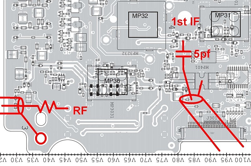
This is the bottom of the bottom board, radio upside-down, front to the left. Using RG-316 Teflon coax (with SMA connector on one end), the IF tap connects to the output of the first IF mixer; the RF tap connects to the jack of the coax that connects the bottom (MAIN) and top (PA) boards.
The IF tap will emit both TX and RX at 124.487 MHz, with several MHz bandwidth. The tap point has a DC bias on it (for diode switching), so the tap requires a DC-blocking capacitor. 5pf works well.
The RF tap will emit transmit RF at the dial frequency, and antenna receive filtered by the radio’s bandpass filters. On TX, it is the low-level signal that drives the PA board. The connection point shown has capacitors on each end, so no blocking capacitor is required for the tap. However, the signal is a bit too hot on transmit, and the receiver is pulled down some, so I used a 1k 20-turn trim-pot set to around 38 Ohms when feeding the RSP1A. The trim-pot is recommended, as it allows you set the balance of receive signal going to each receiver.
First, we’ll cover the IF tap. If you are only interested in the RF tap, jump to Installing the RF Tap below.
Installing the IF Tap
Following the instructions of a Youtube video, I added a tiny 5pf capacitor to the mixer output, then brought out a little RG-316 Teflon coax with an SMA connector. That connects to the NESDR SMArt, an advanced, purpose-built RTL-SDR dongle with aluminum case, SMA connector, and best of all, a 0.5ppm TCXO (high-stability oscillator). I started out with the Nooelec “Blue” dongle, but its stability just wasn’t good enough for SSB listening, and I was always fiddling with the calibration. Then Nooelec came out with the SMArt, $22, and I jumped on one. The IC-7100 also has a 0.5ppm TCXO, and using WWV I can set it to within ±0.2 Hz at 15 MHz. Then I set the SDR dongle to about ±1 Hz, which is the resolution of the software.
Note: Web articles age, so be sure to research get the best RTL-SDR available. In 2018 the two best are the Nooelec NESDR-SMArt, and the RTL-SDR.COM V.3, which also has a TCXO and adds bias-tee and direct sampling mods. Do not even think of buying the cheapo $15 DVB sticks—they have no shielding, no input protection, and unstable oscillators. A really good RTL-SDR is $23, and a really bad one is $15, so spend wisely and get one you’ll be happy with. The next step up from a good RTL-SDR dongle is the SDRplay RSP1A, at around $120, from HRO, the only USA source. It has 14 bits of resolution, better dynamic range, wider bandwidth, and bandpass filtering, so is an excellent choice as a multi-purpose wide-band receiver, but is overkill for use only as an IF panadapter, where the V.3 is sufficient.
A few days after receiving the 7100, I got out the tools and decided to follow a Youtube video and add an IF tap and RTL-SDR dongle.
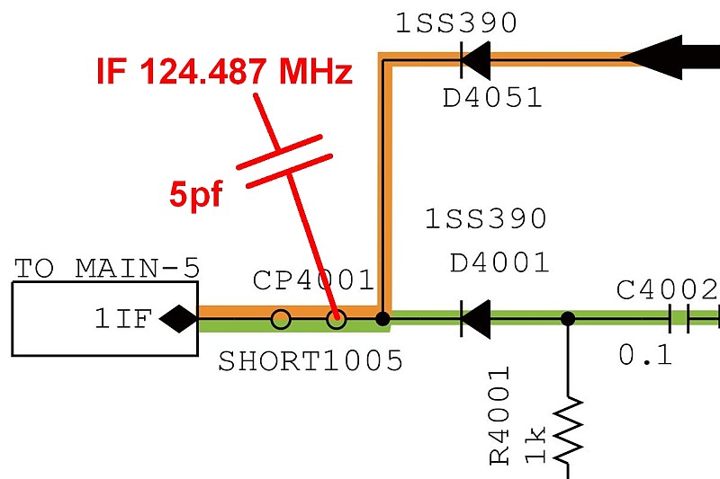
Looking at the IC-7100 Service Manual, schematic MAIN-6, we locate the point in the first IF that is after the mixer, but before the buffer and roofing filters. The point labeled SHORT1005 is a “via,” a tiny sleeve that goes through the PCB.
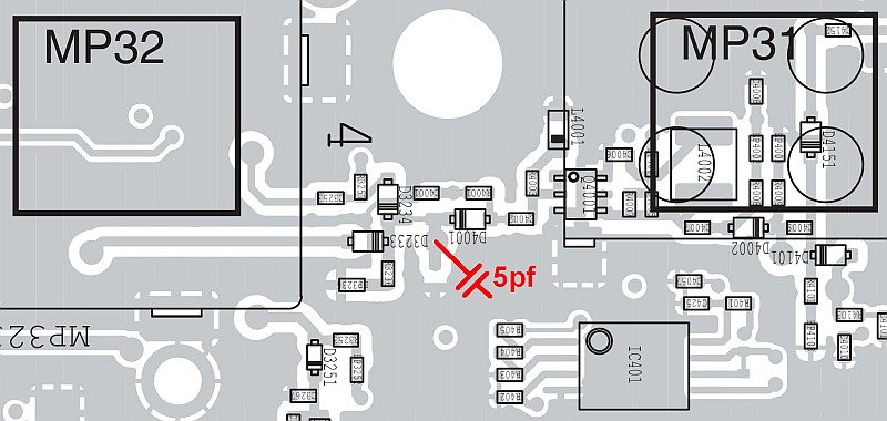
The via is located right there, near D4001.
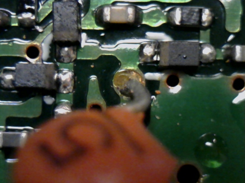
Using very small solder and a fine-tipped iron, apply a tiny bit of solder to the via, and the 5pf capacitor leads. Then set one lead atop the tinned via and heat the lead until solder melts together.
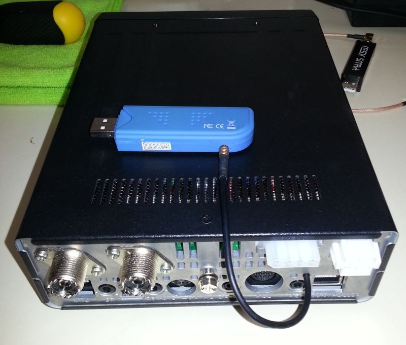
I first used the Nooelec Blue that I already had. I cut the cord off its little (useless) antenna.
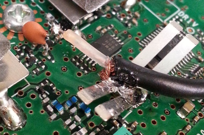
This mess is why you don’t solder RG-174…
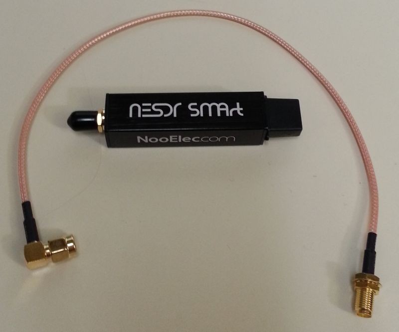
Then I ordered this Nooelec NESDR SMArt, and a little 12-inch cable. I got one with a female SMA on one end and a right-angle male SMA on the other end, so I could use either one and cut the other off.
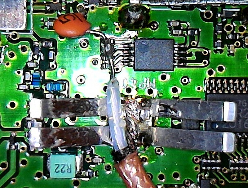
The RG-316 Teflon coax doesn’t melt when soldering. The coax shield solders to the center of the butterfly spring, providing a good anchor for the coax. NOTE: Bad photo! The coax center connects only to the 5pf cap, NOT the pins of the nearby IC! The connection is hovering well above it.
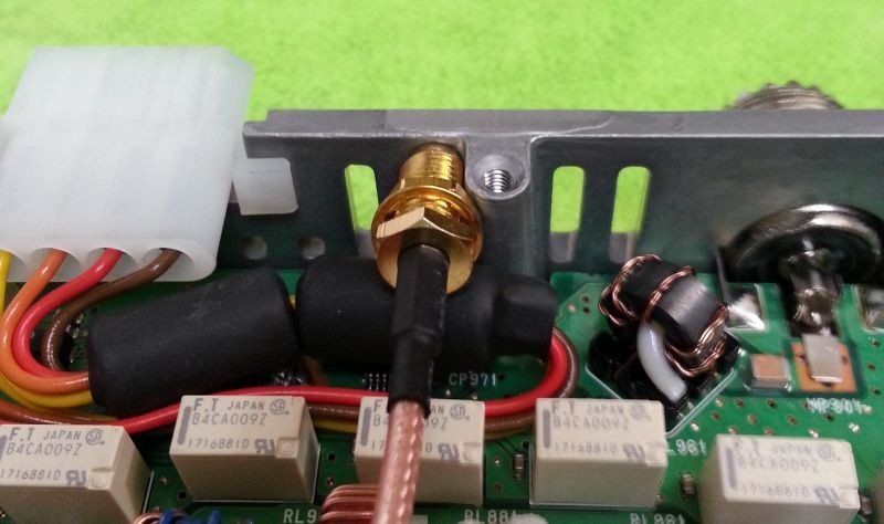
The hardest part was deciding where to bring the cable out. The 7100 isn’t like a larger desktop radio where you plenty of extra rear-panel space. I really wanted to use the chassis-mount female, and not have a pigtail dangling out of the radio. Here? Nope. Some people have drilled through the vent slots, but it requires rearranging the cable (and its ferrite beads) that goes to the Molex antenna tuner socket.
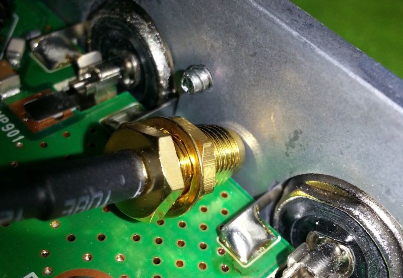
There’s room for a hole only here, but alas,
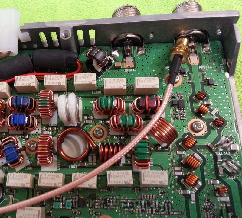
I’ll not run the coax across high-power RF components—on transmit the induced RF would surely blow the dongle, and probably the IF mixer and buffer, too. Don’t run the coax anywhere near high-power RF components! No, coax shields do not block external magnetic fields…
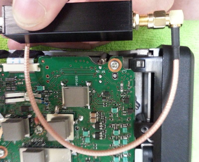
Maybe come out the front! Drill an eighth-inch hole in the side of the front plastic cover, and loop it around like that! But I couldn’t see a place to solder the shield on that side of the tap capacitor. In retrospect, I should have done it this way, and later I did (see the RF Tap section below). If you do this mod, consider bringing the cable out the front. The further the dongle and cable is away from the RF deck, the better.
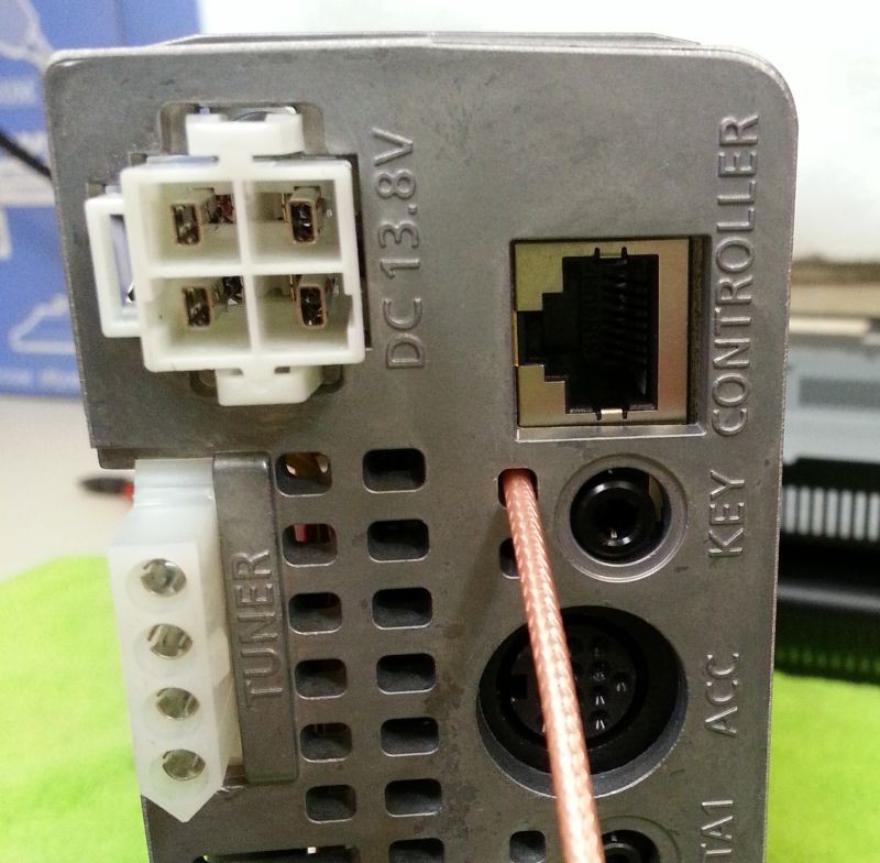
So I went back to plan A and came out here, as before.
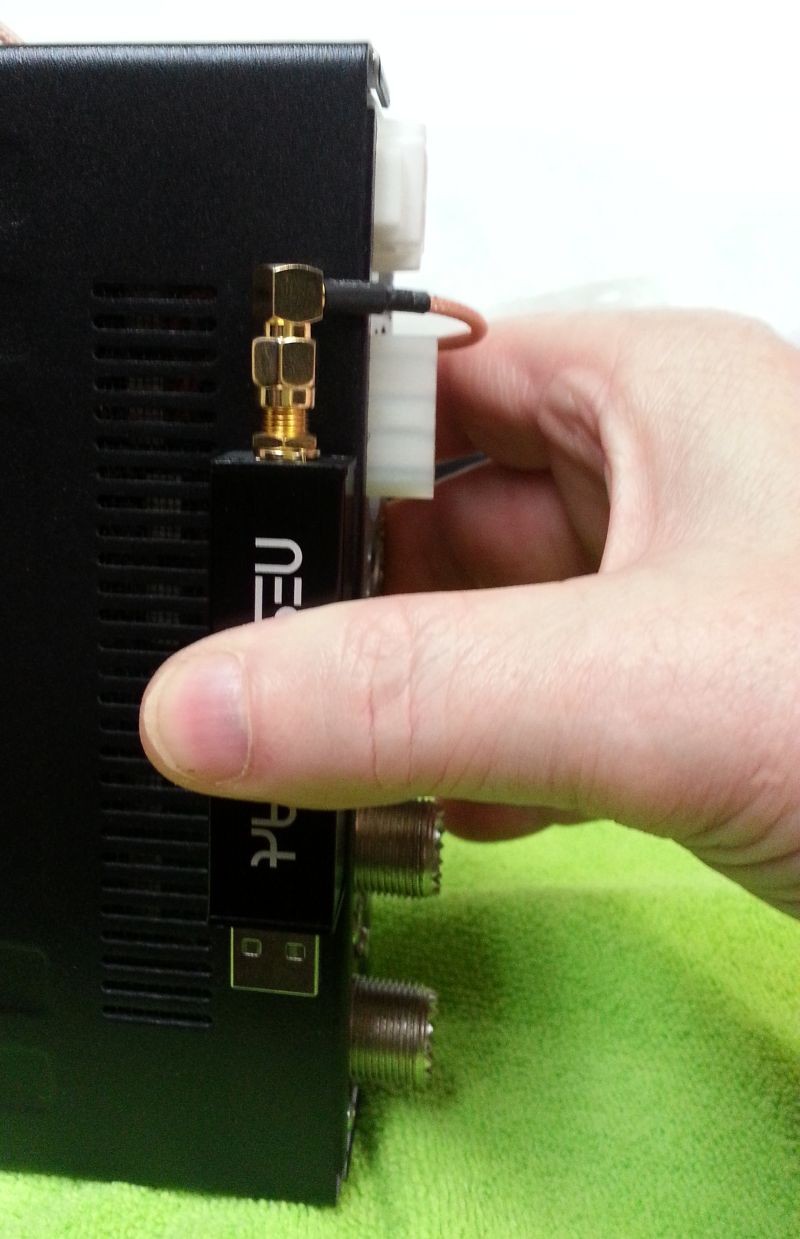
Set the dongle on top (or where ever you will place it) and adjust the SMA pigtail length.
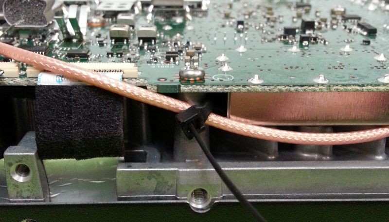
Tie off the cable here so it can’t be pulled. The only notch in the radio’s cast aluminum chassis from top to bottom is where the 2 ribbon cables go. As you pull the cable tie tight, adjust the RG-316 coax for a bit of slack, so it doesn’t mash against the delicate ribbon cables.
(Better idea: come out the front, as shown in the RF Tap section below.)
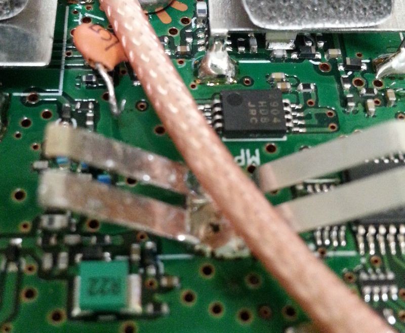
Measure the exact length to the capacitor lead and cut.
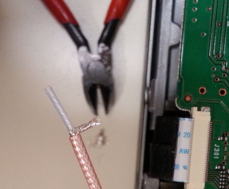
Dress out the end, trim the shield and tin both leads. Don’t work above the PCB!
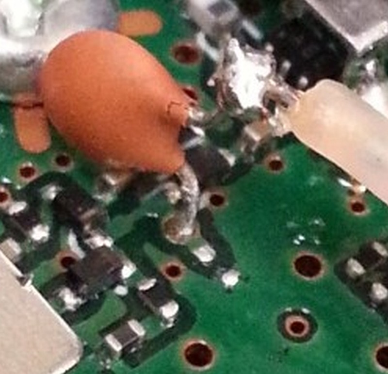
Here, from the first dongle install, is the picture of the actual capacitor connection point. It’s all very tiny, and you need a headband magnifier. Form and tin the cap’s leads, then quickly tack-solder it by heating the lead, not the PCB. Note that this is the proper place to tap. It’s after the 1st IF mixer, but before its buffer amp (which puts out way to much signal for the RTL-SDR), and is before the roofing filters. So the dongle gets several MHz bandwidth, and benefits from the radio’s bandpass filters, pre-amp, and attenuator. But from this point on, it’s two separate radios. So, for example, adjusting a filter on the 7100 will not affect the SDR, and vice-versa.
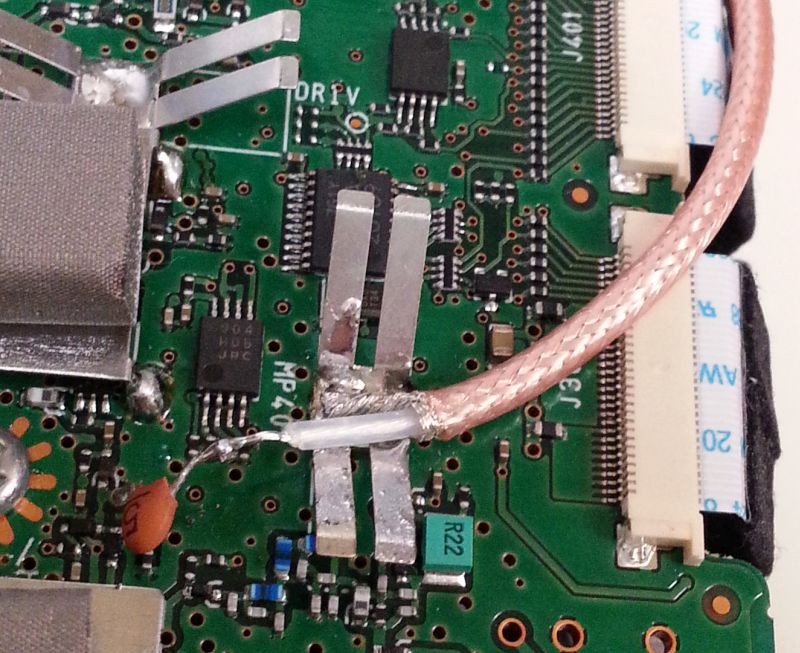
Here’s the connection of the new coax. Solder the tinned shield in the middle of that butterfly case-ground spring, and tack the tinned center conductor to the tinned capacitor lead. Don’t go adding solder above the PCB! One drip and some tiny SMT component is toast. If you absolutely do need to add a bit to get it to tack properly, at least lay some damp paper over the PCB.
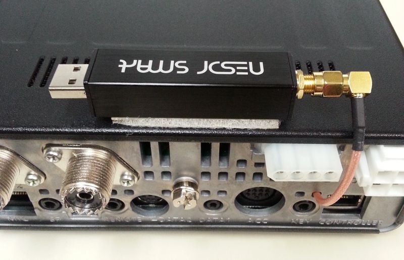
Test it, then put on the covers, and stick the dongle down with Velcro.
I forgot to mention, you’ll need to order a USB-A male to female extension cable. Get a good shielded 10-footer. But why not just plug the dongle into the computer and use a long SMA cable? Because the RF cable is lossy, but the USB cable isn’t. Also, you don’t want a long RF cable picking up RFI or noise and injecting it into the receiver, so keep it short!
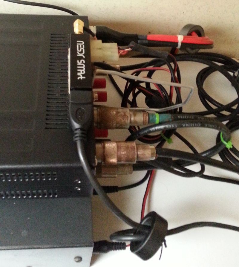
Connect the USB-A extension. Note the FT-140-77 toroid I put on the USB cable, to keep stray RF out of both the dongle and the computer. It’s a good idea to use one on each end of the USB extension cable. You can push a USB-A connector 2-3 times through an FT-140, and RF choking goes up by the square of the turns count. So, 3 turns is better than 9 snap-on chokes.
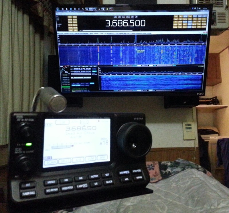
And there it is, running HDSDR. Panadapter on the big screen! Yay!
Installing the RF Tap
About a year later I purchased an SDRplay RSP1A and installed an RF tap in the 7100 to feed it. Yes, I could have simply connected the IF tap to it, but the IF tap doesn’t let you tune the SDR to a different frequency than the radio. The RF tap will allow the SDR to be used as a second receiver and tuned anywhere. Indeed, with SDRuno you can have several virtual receivers, though they must all be within the SDRplay’s current bandwidth, which will cover 1 or 2 ham bands.
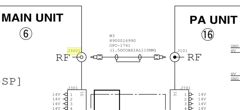
Following around the signals in the block diagrams and schematics, one finds that this little coax runs low-level RF both ways between the main and PA boards. On receive, it’s signal is antenna level, and on transmit it’s around -30dBm (~S9+40) to the SDR.
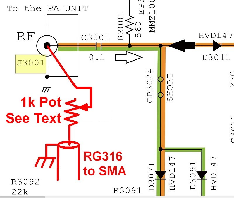
The jack at either end will do, but I chose to use the one on the Main board (bottom of radio) at J3001, since the board is clear in that area. Note the DC blocking cap C3001.
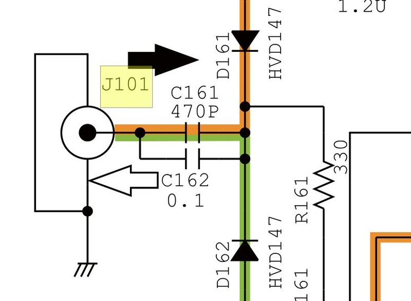
The other end, on the PA (top) board also has DC blocking caps.
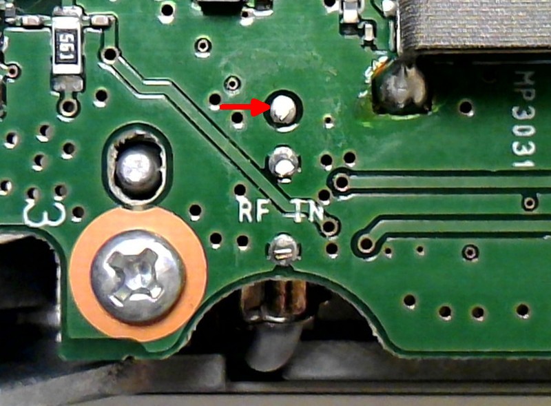
The RF tap point. This is on the bottom of the bottom board, radio upside-down, front to the left.
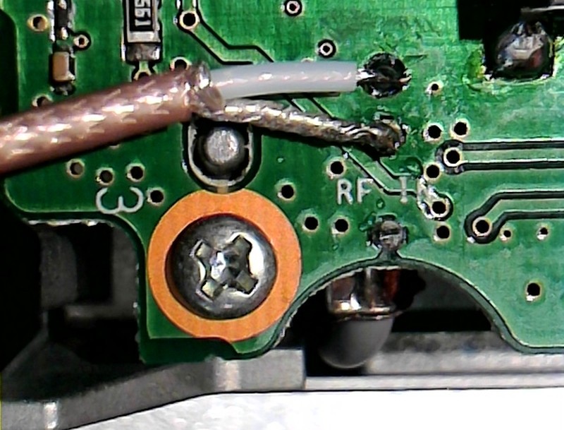
First, I made a temporary connection, to determine the RF levels, and receiver loading. The receive level is about the same as at the antenna jack, and is suitable for feeding the SDR. However, connecting the SDR divides the signal and lowers the receive level by about 3dB. The RF level on transmit is a little too high for the SDR, and I don’t want to divide the power going to the PA board, so I added a 1k-Ohm trim-pot to enable adjustment of the RF going to the SDR. I started testing with it set about 500 Ohms, but the SDR signal was way too weak, so I reduced the resistance until the 7100’s S-meter dropped the tiniest amount, which was at 38 Ohms. If you use a different SDR, you’ll need to determine the proper resistance. Use a signal generator set to 50μV (-73dBm), which is S9. The setting I used dropped the SDR a little more (~5dB) than the 7100 (~1dB), as I wanted to maintain good sensitivity in the 7100.
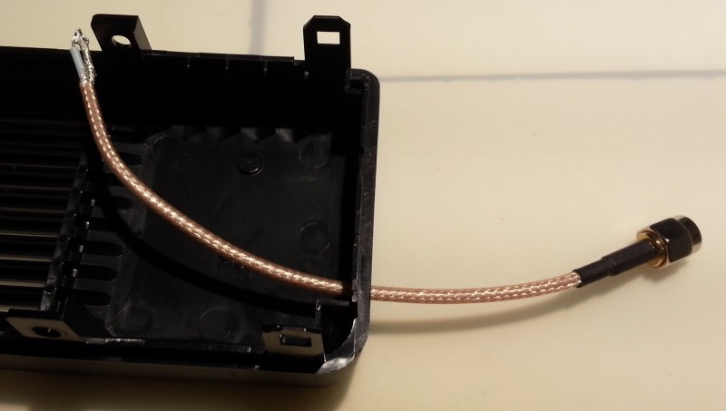
This time I came out the front of the radio, as I should have before. I drilled a hole in the side of the front cover here,
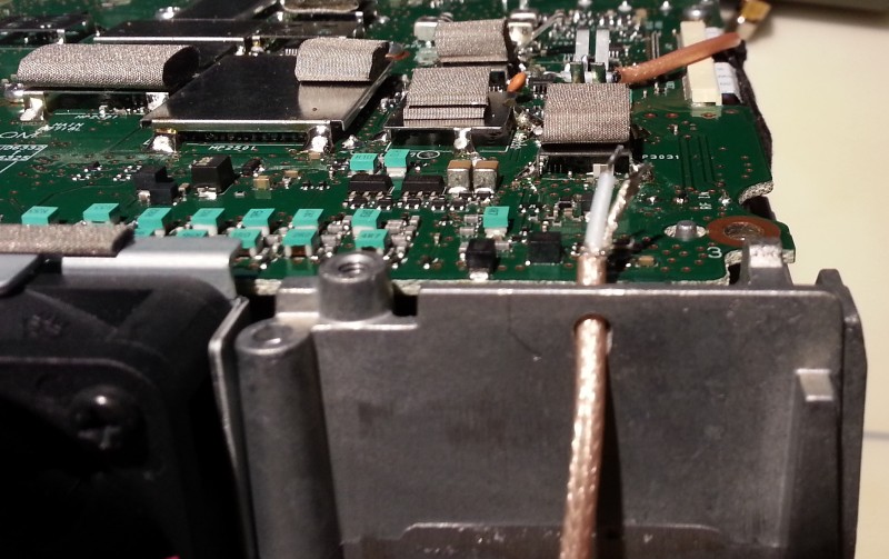
and in the front of the chassis here. Be sure to collar the 1/8th-inch drill bit (I used electrical tape), and turn it very slowly, so that it can’t auger through and hit the PCB. Wallow the hole a little to remove sharp edges.
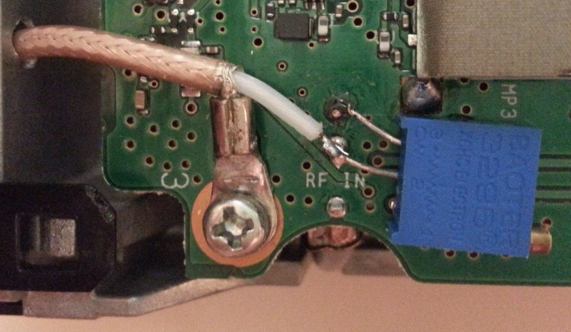
After all the testing, I tinned and formed the leads on the trim-pot and stuck it down with a small dab of hot-glue. Instead of soldering the shield to the jack’s ground pin, I soldered a small ring lug to it and put it under this PCB mounting screw, thus providing a solid anchor for the coax. Solid anchoring is very important, as tugging the cable would otherwise damage the PCB.
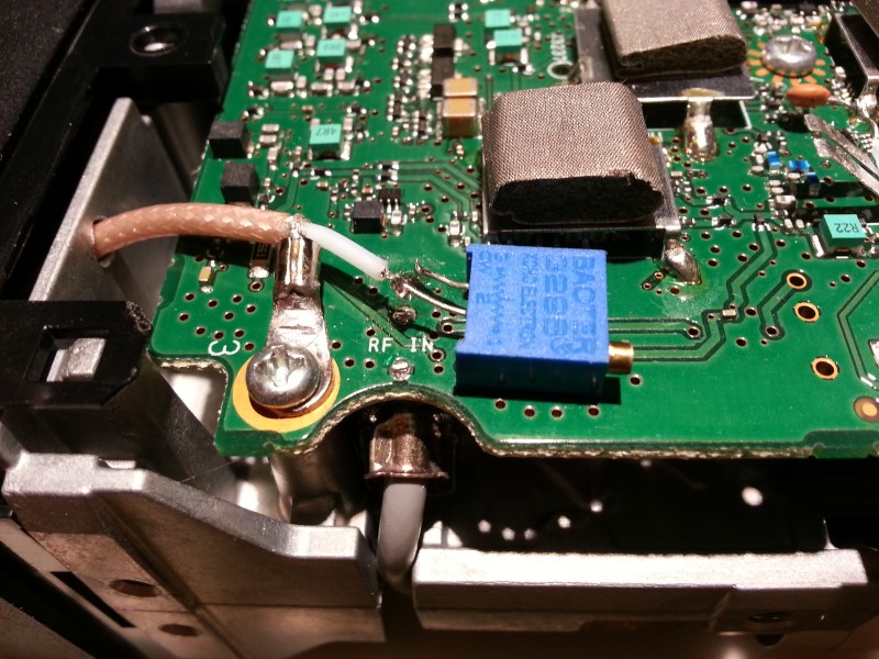
Angle view.

Side view.
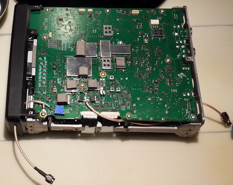
Full view of both taps. While it was open, I should have re-done the IF tap and brought it out the front alongside the new RF tap, but well, I forgot… I’ll probably just remove the IF tap, the next time I open the radio.
NOTE that the proper way to do this would be to install one or two chassis-mount SMA female connectors in the left side of the front cover, and not have dangling pigtails. That’s what I’d do if starting from scratch.
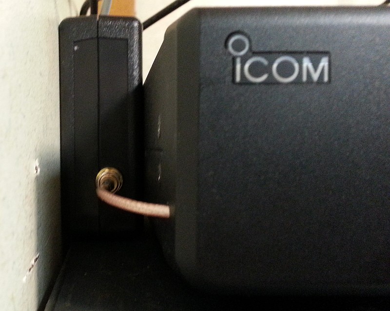
My cable was a bit too short to lay it on top, but it slips right in there between the radio and the wall.
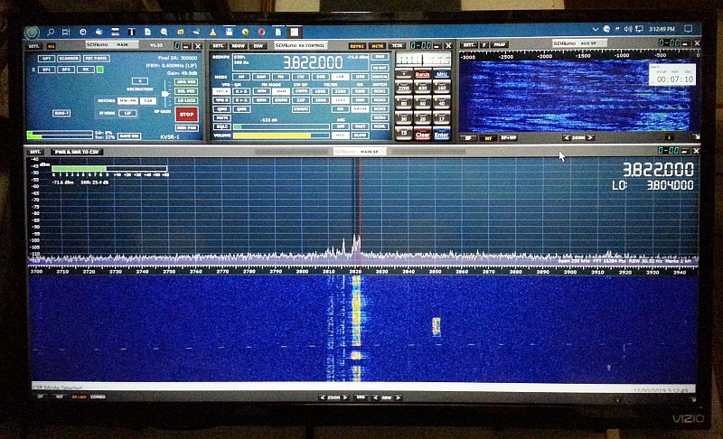
And there it is, SDRuno on the 32 inch TV! Another upgrade succesfully completed!
Hardware: What to Buy?
There are many SDR receivers available, ranging from twenty to several hundred dollars. For adding a panadapter to a ham radio, the RTL-SDR.com V.3, for around $23, is more than sufficient. It has an aluminum case, SMA connector, a very stable oscillator, and best of all, software-selectable direct-sampling mode for operation below 25 MHz. Thus, it is suitable for either IF or RF taps. At the time of this writing, the V.3 is probably the best RTL-SDR dongle you can buy.

The RTL-SDR.COM V.3 - read about it on rtl-sdr.com, buy it on Amazon.
The RTL-SDR dongles have one major drawback: no filtering! That means you will see spurious signals all over the place, most of them from powerful AM and FM broadcast stations. While you can (and will) need to buy band-stop filters, that will add to the cost, and what you end up with is a train of gadgets screwed together with SMA connectors, and when you do want to receive broadcast stations, you have to unscrew a filter or two. However, it’s not a problem if you use the RTL-SDR dongle only on an IF tap, as that will use the transceiver’s band-pass filters.
While even the best RTL-SDR dongle is just an improved DVB-T (European TV) receiver, a much better solution is a well-engineered, purpose-built SDR, such as the SDRplay RSP1A. Yes, it’s $100 more than a RTL-SDR dongle, but let’s consider what we are getting! 1kHz to 2 GHz, 14-bit direct-sampling, high-stability oscillator, AM & FM & DAB broadcast band filters, 11 band-pass filters, up to 10 MHz bandwidth, and an impressive dynamic range and low noise floor. In other words, it has performance comparable to the receiver in your expensive amateur transceiver.
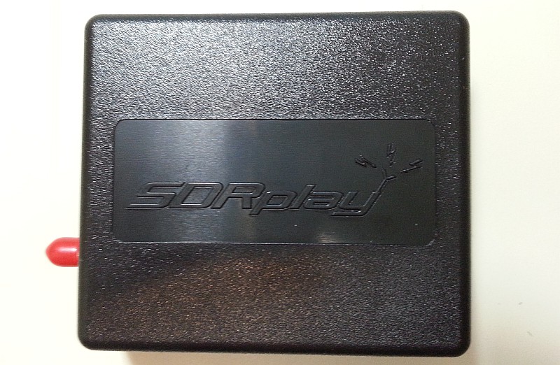
On the outside, the RSP1A is just a 3-by-4-inch plastic box with two jacks. But all the goodies (including proper RF shielding) are on the inside! SDRplay receivers are made in England, and the only dealer in the U.S. is Ham Radio Outlet.
In deciding between the two, another consideration is that an RTL-SDR on an IF tap cannot be used as a second receiver, as it always receives whatever the transceiver is tuned to. But the SDRplay on an RF tap is truly a second receiver, connected to the same antenna as the transceiver, and by simply disabling CAT control, it can be independently tuned. In fact, you can start several virtual receivers in SDRuno, as long as they are within that 10 MHz range! Dual (or multiple) receivers are handy in several scenarios. For example, contesters like to listen to both sides when working in split mode. Someone in a net may need to also monitor another net. Or, you may wish to monitor several frequencies to see (hear) when they become active. Or monitor one or more digi-modes, some of which operate on a schedule. You might even want to record other frequencies.
Beyond the panadapter and second-receiver uses, the RSP may be connected to a dedicated antenna (with proper overload protection) and used for purposes independent of the main transceiver. For example, as a VHF/UHF scanner, broadcast receiver, NOAA weather satellite pictures, aircraft tracking (ADSB); not to mention piping its output to a plethora digital mode decoders, without tying up your main radio! But I digress—back to hardware…
You will, of course, need some cables. For an RTL-SDR dongle, a USB-A male to female extension; for the RSP, a USB-A to USB-B cable. Ideally, they should be shielded and have a ferrite choke or two. For the RF side, you’ll need some RG-316 jumpers with SMA connectors. Look on Amazon for whatever cables you need, and read those reviews! Many cables are junk, particularly in a high RF environment, and few things are more frustrating than random computer glitches caused by RF on USB cables.
Finally, any time you’re connecting radios with computers, it’s a good idea to have a dozen FT-140 toroids on-hand. Amidon is the place to go for toroids.
SDR Software
The best software (IMO) for an RTL-SDR dongle is HDSDR. It’s not as pretty as more recent SDR software, but it provides ample features for IF tap operation, and it just works, very well. Note that its rather sparse-looking user interface hides many useful features that stay hidden until you need them. It has some learning curve, as do they all, but it is worth the effort.
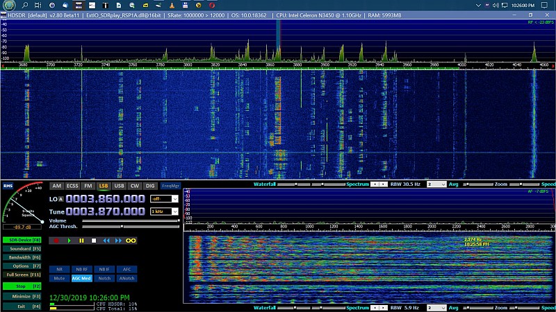
This is HDSDR, which I used as a panadapter for a year. Here it is now running the RSP1A. To use an RSP with HDSDR you’ll need to download the ExtIO installer package from the SDRuno site, and during install, tell it to install to your HDSDR program folder.
For the SDRplay brand SDRs, the best one to use (IMO) is SDRuno, as it fully supports their RSP radios, and it looks great! But be warned, SDRuno has a pretty steep learning curve, and many things about it are just plain frustrating, particularly the way it uses several windows that do not snap or dock, requiring careful positioning. Look for a program called Aqua-Snap to make it easy to snap SDRuno’s windows together. This is a complex program, and reading the whole manual is essential, as many features, controls, and settings are not readily evident.
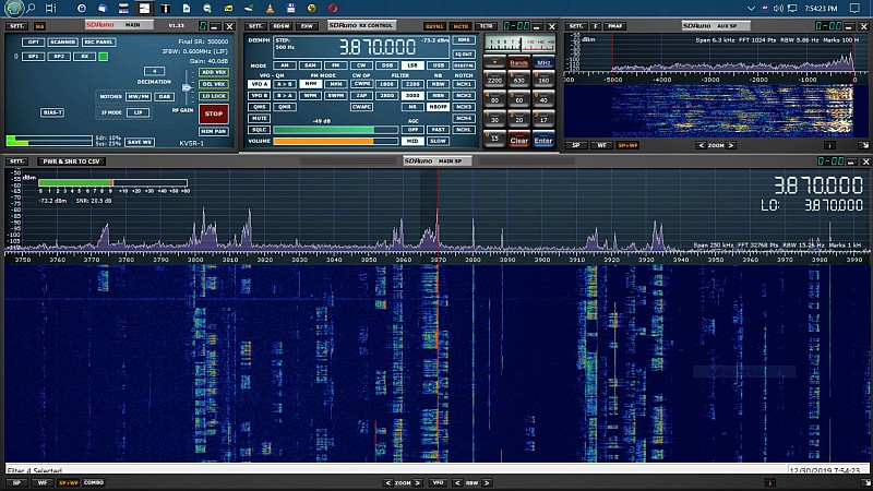
This is SDRuno, with the essential windows opened and arranged in a Workspace.
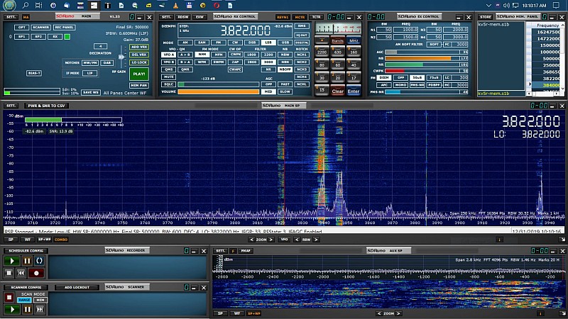
This is another SDRuno layout I made and saved, with all windows showing, and the spectrum/waterfall in Combo mode.
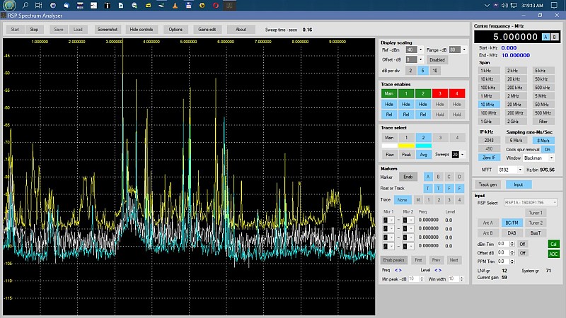
The SDRplay RSPs are not just radios, they are also well-calibrated (in dBm) for use as test equipment. This is Steve Andrew’s Spectrum Analyser software, available (free) on the SDRplay web site. Here I was sweeping 0-10MHz on my 80-meter doublet; note the hump between 3 and 4 where the SWR is lowest.
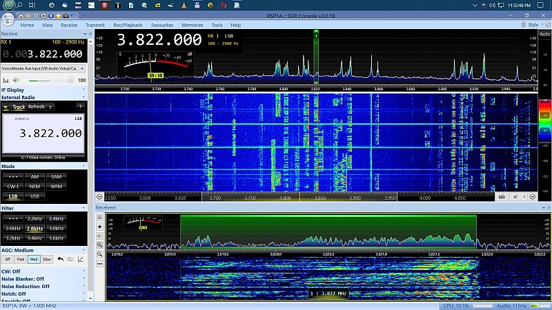
This is the RSP running in SDR-Console V.3, a nice full-featured SDR program by Simon Brown, of Ham Radio Deluxe and DM780 fame. Like SDRuno, it has a considerable learning curve, and a few annoyances. But, like the HRD suite, it uses an MDI interface where everything can be moved around, resized, and docked to your liking. It is much more customizable than SDRuno. If you like the HRD suite, you’ll like SDR-Console.
I’ve tried a couple others, but I didn’t like them, as each one was missing features, or quirky to operate, or just plain buggy. But they are all free, and are works-in-progress. If you run Linux, your options are limited to Cubic-SDR and GQRX, both of which are somewhat limited and quirky to operate. They’re okay for general SDR use, but not for interfacing with a ham transceiver.
IC-7100 and SDR Frequency Calibration
Frequency calibration is very important, particularly with ultra-wide-band radios like SDRs that can receive to 2 GHz. Consider that a 1 Hz error at 10 MHz becomes a 1 kHz error at 1 GHz! That error is fine for decoding HF digital signals, but not for UHF. If your interest is just casual listening, then a few cycles off is okay.
First, calibrate the 7100 (using Set → Functions → REF Adjust) by tuning to WWV (or another frequency standard). Switch the radio back and forth from CW to CW-R, and carefully adjust REF Adjust until the CW offset tone equalizes. For greater accuracy, use the USB audio output to a computer and read the audio beat frequency on software that will do so, such as MixW in PSK mode, on the AFC reading in the status bar. You’ll notice there are actually about 3 encoder pulses (of the main tuning dial) per percent reading in REF Adjust screen. By moving the dial the smallest possible amount, you can get to within +- 0.2 Hz, when switching CW to CW-R.
(For detailed instructions on calibrating the IC-7100 (and similar Icoms), see my 7100 Calibration article.)
With the SDR on an IF tap, calibrate the HDSDR (set to IF input) as follows: First make sure HDSDR and the 7100 are controlling each other via OmniRig CAT/CI-V. Set HDSDR (and thus, the radio) to exactly 10 MHz, AM mode, and receive WWV on both. Click the ExtIO (or SDR-Device, new ver.) button to open the ExtIO control box and set the PPM as close as possible. Then right-click the ExtIO button to open the RF Front-end Frequency Options control box. Use the Global Offset field to fine-tune the calibration. With that box still open, click the AFC button. HDSDR will then adjust the frequency to synchronize with the WWV carrier. Note the difference (offset from 10MHz) and adjust the Global Offset by that number of Hertz. If the AFC frequency jumps around a lot, use a time standard with a stronger signal, or at a different time of day.
With the SDR on an RF tap, HDSDR (set to Antenna input) provides only the PPM setting in the ExtIO dialog for calibration, but that will get it within a few cycles of WWV at 10 MHz. If using an RSP with HDSDR, download the ExtIO package from the SDRuno download page and install it to your HDSDR directory. It will place several ExtIO dll’s there, and you pick the one for your model of RSP when HDSDR starts (you can delete or rename the DLLs you don’t use). Then in HDSDR, click the ExtIO or SDR-Device [F8] button and a large dialog will open with several settings specific to the RSP, including calibration, which (unlike with RTL-SDR dongles) can be set with 0.01ppm resolution. In HDSDR, tune to a frequency standard, set mode to ECSS plus AFC, then adjust the PPM in the RSP’s ExtIO dialog.
Calibrating the RSP in SDRuno is even easier: In RX Control window, click SETT, scroll right to CAL tab, follow instructions there; set mode SAM and DSB, tune to a frequency standard, and click the AUTO CAL button.
Now both the 7100 and the SDR are synchronized to WWV (or another frequency standard) as closely as possible. I have found that my 7100 is much more stable than its spec’d 0.5ppm. But the Nooelec dongle, also spec’d at 0.5ppm, is considerably less temperature stable. When the room temperature changes a few degrees, it will go off by several cycles. The RTL-SDR V.3, spec’d at 1ppm, is much more stable than the Nooelec. The RSP1a is even better, almost as good as the 7100.
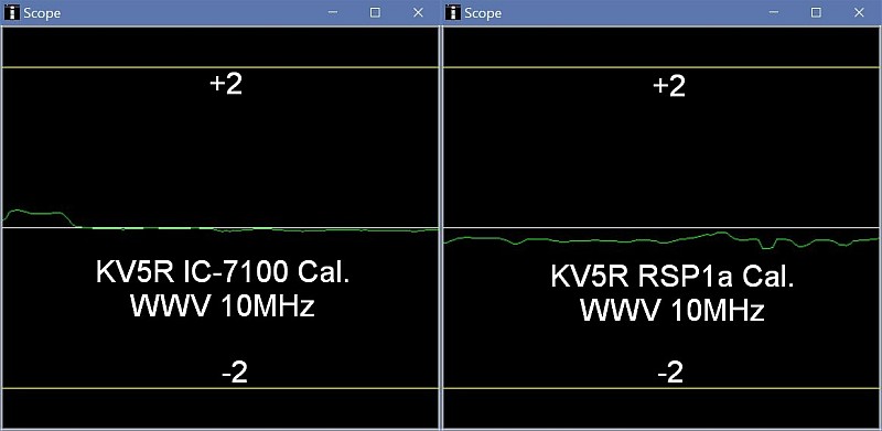
Now that’s what I call getting on frequency!
What’s Next?
Better audio with a boom mic and equalizer!
73, — KV5R

This was really helpful, thank you.
Thank you for the wonderful article I did the RF tab feeding it to a RSA device. I used to thin piece of coax and came out the front of the radio soldering the first and directly to the board and then using the connector to screw directly into the RSA. Was able to use tiny tie wraps to secure the cable to the front I think it works great and since it’s a shack based rig everything stacks up on top with a little double-sided tape and coiled up data cords. Thank you again for your in-depth article.
There seems to be a menu option to switch the ACC/USB output between AF and IF – is that something else, or could you just take the signal from ACC (assuming you’re not also using the USB AF for a digimode)?
The output when set to IF is only 12kHz wide so it’s not useful for a panadapter. It’s the 3rd (last) IF, which is way down close to audio freq range (36kHz+-12 if I remember) feeding the A/D converter that feeds the IF DSP where bandpass filtering is done in DSP.
You can put it in IF mode and feed the USB to computer running audio spectrum software (like Spectrum Lab) and look at the 12kHz, or run Dream DRM software and decode Digital Radio Mondiale broadcasts, which are 10kHz wide upper sideband.
73, –kv5r
For those of us who don’t want to or are not qualified to do all that to our radios, there are other ways.
One is Win4Icom software (love it!) in conjunction with SDR Play, e.g. RSPdx.
I already owned an RSPdx ($200) and the free Uno. So all I needed was an MFJ RX/TX switch ($130).
Thank you for this wonderful write up. I went the RF tap method with a SDR Play. I used a 39 ohm resistor that I had around the shack. The signal coming into the sdr is around -120 dbm. It’s picking up signals but there is no change on the screen if I disconnect the sma feed all together so I feel the signal from the 7100 is far too attenuated. Is it possible the 39 ohm resistor is way too much for my radio? The setup does work if I connect the antenna directly to the antenna.
Make sure you connected the resistor to the right tap point; there’s 2 right together, one is ground, the other is the center of the jack for the little gray coax that goes between the 2 boards. It’s the 2nd one above the “RF-IN” printed on on the board; the one closest to “RF-IN” is ground (do not use). See pictures above; note the connection of my trim pot to the coax hovers above the ground connection, NOT connected to it at all. The ring lug under PCB screw is the only connection to ground.
The resistor goes in series with center of the jack and center of your added tap coax. Also check your resistor with a meter, maybe you put in a 3900; those tiny color bands are hard to read sometimes!
Also check that your sma coax isn’t shorted.
That’s all I can think of.
73, –kv5r
Excellent, thank you for the advice. I decided to redo the connections and they work now so I’m going to blame a cold solder.
There is a loud low frequency buzz, like a persistent bass note, that I hear through the computer headphones and not through the 7100. Do you think there is a filter setting I am missing on sdruno?
hi Harold, would you be interested in installing everything needed to an IC-706 MKII to allow me to use a panadapter? Just wondering. Lee Look
No, I have no idea where you’d tap a MkII for an SDR panadapter. You need to find the Service Manual for it and locate either 1st IF mixer output, or low-level (way under 0dBm) RF point, test the level and frequency coverage, then determine any DC blocking cap or attenuator resistor if needed.
Your other option, of course, is to use external relay switching to parallel the SDR with the antenna on receive, and disconnect and ground it on transmit. MFJ sells a box to do that.
73, –kv5r
I use HD SDR as well, but have one big complaint! Whenever you tune the rig, the waterfall shifts. I haven’t found a way to LOCK the frequency range on the display (e.g. always show 14.150-14.350).
Does it have this feature, just hidden somewhere?
Misc Options -> Keep Tune When LO is Changed.
Works only in antenna input mode, not IF mode.
The center of the waterfall is determined by the LO frequency, so it must be locked, not tracking with Tune freq, for the waterfall to stay still.
73, –kv5r
Ok, this article makes me want to mod my two ‘7100s pronto. Well written, well done and, well, actually even a little inspirational. Thanks! And to think I only dropped by your website because of the ‘7100/WSJT article…
73 de
Scott
AD5U
Hi,
I just did an RF tap following your instructions. I, however, used a larger resistor in series and added an LNA going in to my SDRPlay. While technically not a buffer due to the gain and input impedance; I ignored input impedance and decided to use the gain of the LNA to compensate. The results seem to be fantastic. I used a 100ohm resistor in series with the RF tap that seems to have zero effect on the radio’s sensitiviy; and the LNA boosts that signal to the point the SDRPlay has to disable it’s own internal gain. The LNA on my antenna by itself actually gave an increase in SNR; so it’s internal noise figures are pretty low.
Hey that sounds great!
Just remember the max input on an SDRPlay is 0dBm (1 milliwatt). Using the spectrum analyzer software (from the sdrplay site) will show what level the box is actually receiving.
If you wouldn’t mind, please reply here what LNA you used, where purchased, and does the RSP’s “Bias Tee” setting power it?
73, –kv5r
Hi,
I will grab the spectrum analyzer software and let you know what signal levels I’m getting. I honestly was just fine with “armchair eyeball” quality readings as I’m not relying on the SDRPlay as my primary receiver; this is why my main goal was reducing load on the rig at any and all costs.
I tuned to a local AM station and observed it’s S5 signal strength dropped a bar or two when the LNA was plugged up. I played around with some values and found a 330 ohm resistor seemed to do the trick. There’s even less load on the 7100 and there’s still what I think is a pretty decent signal level coming in to the SDRPlay. I knew what the max input level was and it’s an original I’ve had for about 4 years now; I may not have been too upset if I “accidentally” blew it up and needed to get an RSP2 to replace it. 😉
https://www.ebay.com/itm/9-15V-LNA-Low-Noise-50K-4G-High-Gain-25DB-0-8G-High-Gain-Flatness-RF-Amplifier/353097476355 is basically the LNA I ordered. It’s sold by a lot of different sellers and there are two different versions that look like this; one has this small round transistor and takes 9 – 15 VDC; the other uses a different package and only uses 5VDC. My original plan was to power the LNA off the accessory port’s 13.8VDC output; except it’s not there. I don’t know if this is an oversight in design..or if I blew mine up somehow.
So what I’ve done since then is basically build an AND gate out of a couple of 2N9304s; and drive it with the 8VDC on accessory pin 1 as well as the PTT line. This effectively allows me to kill the power to the LNA whenever the radio is powered off or in transmit (or something breaks and pops the 8VDC regulator)
I’ve got some pictures of the waterfall I’m getting on my website if you want to take a look at those. But so far I’m actually quite liking this setup.
73,
Jay/NQ4T
Ah yes, I have a similar one I use with my freq counter (which likes >500mV input to read stable).
The tiny device is not a transistor, but an MMIC (monolithic microwave IC). You can reduce its gain by reducing the supply voltage (I donno how low it’ll go & stay clean). They can even be used in an AGC circuit, where increasing signal decreases supply voltage.
The one you linked can output up to +16 dBm, which if it ever did, for any reason, would likely blow the SDR. You might consider reducing supply voltage (maybe tack an LM7405 onto it) and/or put a divider across the output (2 VR’s), then reduce input resistance some, til it puts out -73dBm (S9) for a 50μV signal into the radio, thus calibrating the SDR+amp combo to the standard S9.
I’m thinking that reducing its supply (thus gain), and adding some load to its output, will give you a better S/N figure. If a barely perceptible signal is .5μV, adding 330 ohms to that signal may be well below the MMIC’s noise floor. Of course, we rarely need to see a .5μV signal on a waterfall, but it’s nice to see whatever the radio can hear.
I did read the 2 articles about it on your site; very nice, and thanks for the mention.
73, –KV5R
See…I don’t keep up with RF parts since my work primarily has me doing old 8-bit embedded systems (with parallel eproms and everything) and old/outdated audio gear. To me it looks like the same small 4 pin transistor I know I had to tap in my IC-725 for IF.
Some of this stuff I’m learning and taking the “well nothing died” approach. I do know the LNA could possibly blow out the SDR; but…as I said, I’ve had it for three years and wouldn’t mind the “excuse” to upgrade to a newer 14-bit model…..at least then I would know how I need to do something about signal levels.
I do have a signal generator…it’s just super old, unstable, and has no markings for power output. It would still get the job done but I would have to have something wired up so I can get an accurate read-out of it’s power level; the same way I typically used a frequency counter since the dial-calibration was only good for about 30 seconds before it drifted. At that point it probably wouldn’t be too difficult to tweak the levels all around. I may yet wind up getting the multi-turn pot; I wanted a straight resistor for reliability not to mention I didn’t have a multi-turn in my junkbox.
I’ll play around with this further in the future; I think right now I’m just going to use it and see how it performs. I do have some in-line attenuation I can drop in if overload becomes a problem to the SDR. I’m also of the opinion that I’m probably not going to work a signal that is at .5μV…so I’m not worried if the SDR can see it. Thus far it’s been if the radio can hear it, I can see it. I’m also not even relying on the S-meter on the SDR for anything.
But your page was highly important (one of the only ones on google) giving really good details about this procedure to the point I was able to go off on my own tangent rather than debate on where I wanted to solder on my radio; so thank you for sharing a lot of the initial work.
Excellent!
Hi Harold, excellent project. Currently working on an IF tap for my IC-718, but the modification to add an RF tab to have a second receiver is excellent. Checking the diagram of the IC-718 the jumper from the main board to the filter unit (RX to RX) after the T/R relay. On the IC-718 the PA board is separate from the filter board or the main board.
Do you think this could be a good connection point for the RF tap?
Sorry, but I’ve never seen a 718, and couldn’t even guess without seeing a schematic, and then testing a likely RF tap point to confirm the level on TX is well below 0dBm, no DC bias, etc. That will probably be the jumper from Main to PA board; the filter board will be after the PA.
73, –kv5r
Apron you see any benefits for using the hupRF PAT board on the 6100 for an IF interface?
No. It works fine without a buffer amp. Using the 5pf cap at the IF tap, I did not see any reduction in receiver sensitivity with the rtl-sdr connected.
–kv5r