Copyright © 2002-2011 by Harold Melton, KV5R. All Rights Reserved. Feel Free to Link to This Page.
NVIS Propagation
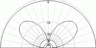
When a horizontal dipole is ½-wave high, it has a wide null overhead, and a main signal radiation pattern shaped like an inverted cone. The reflected wave from the ground is out of phase with the antenna and so causes partial phase cancellation overhead. This makes a good “DX” antenna, with gain at relatively low angles, and a wide skip zone. Problems arise, however, on regional nets and rag chews, because of the skip zone.
As the dipole is lowered below a half-wave high, this inverted cone closes up, the overhead null disappears, and most of the power is radiated upward in a wide lobe shaped like an egg. The reflected wave from the ground is closer to being in-phase with the antenna, increasing the amplitude of the vertical-angle RF power. The effect is somewhat like a 2-element yagi pointing straight up. At a height of .15 to .2 wave, over excellent ground, gain can approach 7 dbi, straight up. Imagine pointing a powerful searchlight straight up at a cloud: The resulting bright spot would provide indirect lighting for miles around! With a horizontal antenna suspended well under a half-wavelength high, we achieve the same effect. We deliberately illuminate the F-layer (which varies from about 100 to 300 miles up) with a wide RF flood, which causes indirect RF illumination of the whole region.
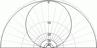
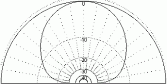
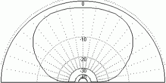
The following graphs show typical elevation profiles for a 75 meter horizontal dipole at various heights. It is apparent that the best NVIS coverage may be obtained at about 3/8ths-wave, or 90 feet high. However, this is impractical for most installations, and antennas much lower will perform almost as well, with the main difference being in the fringe area of coverage. Please note the amounts of power available at various angles, for each height represented.
|
|
|
|
|
|
Figures 1a - 1d: Elevation profiles of the 75-meter horizontal dipole, over average ground.
(These graphs compare closely with the ARRL Antenna Book)
Thus we can see that raising the 75 meter NVIS antenna from 20 feet to 90 feet will add about 8db to the signal ray at 30 degrees, which is considerable, but usually not a sufficient justification for adding two 90-foot supports to the antenna farm. The rule here is pretty simple: If you want a reliable range of, say, 300 miles, use a real low antenna. If you want a little better morning/evening coverage, go to 90 feet as the optimum height. Raising the antenna from 20′ to 90′ simply gives you a little more power at lower angles. Part of this extra power comes in part from the top of the lobe, and in part from reduced ground absorption. Best vertical gain (about 7dbi) is achieved at .15 to .2 wave high, but the 20-foot high antenna will still have a gain of about 5. The best possible SWR may be achieved at about 41 feet, over average ground.
The graphs in Figure 1 do not reflect the whole mechanism involved in daytime 75-meter path length reduction. The next major factor is D-layer absorption, which gradually builds up in the morning after sunrise, and gradually fads away in the late afternoon. Since most of the signal power is at high angles, it continues to penetrate the absorptive D-layer on the way up, reflect off the F2 layer, then penetrate the D-layer again on the way down. At lower angles, the available power is much less, due to ground interaction with the antenna, and the low-angle path suffers additional losses by passing through the D-layer (twice), at lower angles. For example, if the D-layer is 30 miles thick, the high-angle ray will pass through about 30 miles of absorptive D-layer (twice), but the 30-degree ray will pass, at that angle, through 60 miles (twice). (See Figure 2.)

Figure 2: Daytime Path Losses for 70 and 30 Degree Rays, 75 meter band
In Figure 2, we observe two of the three mechanisms that combine to attenuate low-angle daytime signals: (1) Compare the radiated power, which is about 2db below peak at 70 degrees, with the 30 degree angle, which is down about 14db. (2) Compare the distance the rays must travel through the absorptive D-Layer (twice) at various angles: the 30 degree ray has about twice as much loss as a very high angle ray. (3) Add the normal attenuation due to path length (not shown). These three factors, plus a little loss in the troposphere, all combine to attenuate low-angle signals in the daytime. As the sun gets higher, D-layer ionization intensifies, and the effective range decreases further.
From late evening to early morning, 75 meters may spread out to 1500 miles or more, as the D-layer disappears and absorption is no longer a factor in path losses. The typical NVIS antenna pattern shows the signal power at 20 degrees is down 20db, so it is more likely that 1000-2000 mile contacts are made not by the -20db single-hop ray, but two or even multiple hops from the much more powerful rays available at the higher angles. Another factor in “stretching out the band” is the Pedersen ray hop, a mechanism that may be roughly described as ducting in the F-region of the ionosphere. One unfortunate effect of the band “going long” is that many thunderstorms will exist during the warm months somewhere within that giant coverage area. This leads to a great deal of static noise that tends to render the low bands rather useless in the summer, at night — particularly for weak-signal contacts.
In the morning, the sun gradually reestablishes D-layer ionization. It starts absorbing signal power like a giant blanket of attenuation, and its effect increases steadily (more or less) as the sun gets higher. With the NVIS antenna, the low angles where RF power is lowest will become useless out at some point, and the practical signal path distance will draw in to two to three hundred miles radius by mid-to-late morning. This is because most of the signal power is at high angles, and only the main lobe of the antenna is powerful enough to penetrate the D-layer twice. By late-morning (typically), signals beyond 150-200 miles usually become very weak, then inaudible. Raising both antennas substantially (to 125 feet) would provide more power at lower angles and thus increase the range and/or time available, but this is usually quite impractical. The practical solution is to switch to 40 meters, where D-layer absorption is much less and the antenna is twice as high in terms of wavelength. Switching to 20 meters will give nationwide coverage, but with a wide skip zone, assuming the F2-layer is undisturbed. Amateurs, short-wave broadcasters, military, maritime, and aviation stations regularly switch frequencies with the day-night cycle, to maximize reliable signal levels at a given distance.
Of course, the “numbers” are widely variable, depending on prevailing ionospheric conditions and the environment of the antenna, particularly ground conductivity. The “numbers” are roughly based on carefully logged US Army tests, where they compiled the percentage of messages accurately passed, for various frequencies at various times of the day and night, and generated frequency-time charts There are occasionally exceptions, but this article is concerned with reliable tactical communications, not occasional exceptions caused by unusual, atypical band conditions.
All of this explains why the reliable, effective path length on 75 meters contracts and expands with the day-night cycle.
Another consideration is ground quality, consisting of conductivity and dielectric constant. The power lobes and nulls of an antenna’s radiation pattern are created by the distant mixing of the direct and ground-reflected rays, which may be in phase for a lobe, out of phase for a null, and everywhere between for the intermediate levels of power. The ground’s conductivity in the immediate vicinity of the antenna affects the feedpoint resistance and degree of power absorption. The ground quality out to several miles will affect the radiation pattern. Excellent quality ground, such as sea water, will provide the best results, while poor quality ground will absorb more power and substantially shift the phase of the reflected ray, greatly reducing power at low angles. Variations in ground quality from one location to the other explains why one station with a relatively poor antenna may enjoy much better signals, over very good ground, while another station with a highly-optimized antenna may have a relatively poor signal, over poor ground. Since ground quality is what it is, the operator with very good ground need not go to extra trouble to optimize his installation, while the operator with poor ground should optimize his antenna to the greatest practical extent. Average ground is considered to be 5 milliSiemens per meter (mS/m) and a dielectric constant of 13. The topography of the land in the vicinity of the antenna also affects the pattern. The height above average ground affects the feedpoint resistance as follows:
| Meters | Feet | Ohms |
|---|---|---|
| 4 | 13 | 8 |
| 6 | 20 | 15 |
| 8 | 26 | 25 |
| 10 | 32 | 35 |
| 12 | 40 | 46 |
| 14 | 46 | 57 |
Table 1: Feedpoint resistance of a center-fed, resonant
half-wave horizontal wire dipole, over average ground.
In Table 1, the dipole was modeled over average ground, at various heights. For each height, the dipole length was optimized to resonance. It is apparent that regular dipoles should be mounted about 41 feet high, if the lowest possible SWR is to be achieved, when feeding with 50-ohm coax. Alternately, a folded dipole may be placed at about 16 feet. Since there is a 4:1 transformation with folded dipoles, the feedpoint resistance will be around 50 ohms. The folded dipole will also have considerably broader bandwidth.
A desirable effect of the NVIS vertical lobe is the reduction of received atmospheric static from distant storms (in the daytime), since most atmospheric static comes in from angles below about 15 degrees. Narrowing the vertical beam width of the antenna reduces the noise further. This is accomplished by lowering the antenna until the best signal-to-noise ratio is achieved. Alternately, the antenna may be raised to 0.2-wave and a reflector element installed underneath, on the ground, to create a 2-element yagi thereby narrowing the beam width and increasing the gain. This will improve the s/n ratio further, on sites with poor soil. Experience shows that storms may be heard when they are within the antenna’s effective area of coverage, which is much greater at night than in the daytime. When the storms are nearby, no amount of antenna fiddling will improve the static — but if your contact is at, say, 150 miles, and the storm is at 300 miles, lowering the antenna will certainly improve the signal-to-noise ratio by reducing the effective signal radius to exclude the storm.
The frequency to be used at any particular time is selected to fall between the vertical MUF (the highest frequency that will reflect back down from nearly straight up), and the upper frequency end of severe D-layer absorption. Typically, this is 40 meters in the daytime and 75/80 meters at night. 160 meters may be used in the wee hours, if RF begins to break through the F2 on 75. In actual practice, 75 may be used for regional contacts from about 5 PM to about 9 AM, and 40 meters will carry you through the day from 9 to 5. There are several exceptions worth noting: (1) 75 may be useless at night, in the stormy months, due to high static — and 160 certainly is. (2) 75 may drop completely out in the wee morning hours due to failure of F-layer reflection. This is when 160 may be employed, assuming the static will allow it. (3) 40 may drop to unusable levels during the day due to solar activity. Other bands will be affected as well.
Another factor to consider is groundwave. If the stations are close enough, the groundwave and skywave will mix in the receiver, and cause multipath distortion, due to the considerable difference in path lengths. For example, for stations 10 miles apart, the groundwave will travel 10 miles, but the skywave will travel 200-300 miles. For this reason, groundwave must be reduced as much as possible. This is done by both stations lowering their antennas to the practical minimum height. This is usually 10-15 feet across open spaces, and 4-6 feet on fences.
Some people operating mobile have noted a small “dead zone” that extends several miles outside of groundwave range. This may have one of two causes, or both. First, the fixed station is running NVIS, but the mobile is running a vertical whip. RF power arriving from directly above the whip cannot induce current into it. This is why military vehicles are instructed in their Field Manuals to tie the whip down. Second, some researchers theorize that the vertical NVIS lobe has a tiny “hole” right at 90 degrees. The reasoning for this is that the up-going wave and the down-coming wave cannot occupy the same space without phase cancellation — so we might say that there is a “skip zone,” albeit a tiny one. The author believes that both of these mechanisms may come into play in certain circumstances.
Continued…


Hello,
do you have more details on the D-Layer Attenuation … Figure 2: Daytime Path Losses for 70 and 30 Degree Rays, 75 meter band ….
Is it dependent on the Local time, SSN, Latitude etc. ???
Do u have any supporting papers on this subjects?
nearly no nformations on that subject in the Internet
Many thanks and 73
Gerald /DL3KGS
Hi Gerald,
The D-layer is directly ionized by sunlight (UV), so the higher the sun angle, the denser and thicker the D-layer ionization. Because it’s relatively low, molecules are closer together and de-ionize easily, so it takes lots of direct sun power to keep splitting off electrons.
It absorbs RF, more at lower frequencies, very little at if any at 20 meters and above. That’s why, in the daytime, AM broadcast and 160 meters is ground-wave only, and 80 meters is greatly attenuated. 40 goes through pretty well, and 20-10 goes through it easily, even at very low angles (DX).
I don’t know of any papers specifically about D-layer, but any book on HF propagation will cover it, to some degree.
73, –KV5R
I agree this is excellent reading, though I do have one gripe from short-sightedness of the authors: Given the very deep minimum we’re in as I write this (2019) with a very weak cycle and that the next perhaps few cycles are expected to be as weak or even weaker, I the statements about 160m not being useful “except in the wee hours of the morning” are clearly wrong right now, especially in the winter. In addition, 40m many times has appeared to be long all day (IE, D-layer ionization never got up to snuff even for that band).
I think the text should be modified for this “new” normal. (Well, new in our modern times.) I’ve even been considering asking DX Engineering and others who make NVIS kits to make one that can do 160m, though they’re not hard to build. What do you think?
Thanks, Mike
I wrote this article 17 years ago, but was careful to to state in several places that performance figures are highly variable, particularly ionospheric conditions. I don’t think that was “short-sighted.” I think all active hams know we are currently experiencing very atypical conditions, and will adapt accordingly. The general principles of NVIS/short-skip operation laid out in the article are still applicable.
I do hope to see a considerable increase in 160M activity this winter, as I hear many QSOs on 80 talking about getting something up for 160, though many find it very difficult to cram that much wire into a city lot. End-fed quarter-waves, usually inverted L, are frequently discussed, but they tend to be disappointing performers without a bunch of radials, which are often impossible on city lots. A perhaps better option is putting up a dipole in a square or Z shape, which require 4-5 supports, but that may also be impossible, due to restrictions. In any case, getting out a good signal on 160 is quite challenging for those without a sufficient amount of unrestricted real estate.
73, –kv5r
Since I’m new to loops and the ARRL antenna book had very little info on actual designs, I needed an expert to answer. The photo enclosed shows a square NVIS loop for 40 meters. My question is the box at the bottom. Doesn’t really appear big enough for a variable capacitor of much size. I believe the antenna is only 40 meters so from the info I don’t believe it is tunable. So my question is, can you build a dedicated 40 meter loop for TX/RX that is not tuneable? Also I don’t see a driver loop, could that be in the box? Or would the box just be a balun? I tried to contact Z21LV the builder of the antenna but could not reach him.
Here is a link to the image it is at the bottom of the page. https://www.qrz.com/db/Z21LV
I can’t tell by looking at it… He says it’s inductively coupled and has a 2:1 SWR bandwidth of 20kHz, so it’s not tunable. I’d guess the little box has a toroidal transformer in it, as the feed-point impedance of such a loop would be very low. Small loop antennas are generally quiet, but low efficiency and very narrow bandwidth. Without a variable cap it’s a 1-frequency antenna built for 7070.
If I was gonna put a 40 meter NVIS antenna on a truck it would be a loaded horizontal dipole on a short mast, something like a pair of Hamsticks or Buddipole. Or maybe back-to-back Wolf River coils with whips, to make it adjustable.
73, —kv5r
Being new to Amateur Radio, I find an affinity to this type of information. I’m like a sponge and have learned a lot from reading this epistle. My older brother (I’m 68 and he is 74) hs spoken to me about these things but in terms I don’t easily follow. However, this is so well-written that I find now I’m “clearing the log jam” in my brain!! Thanks for feeding this good information – keep it up please!
KN4HEW, Joe
My antenna was just above my roof here in the Tampa Florida area. I don’t have any CCR’s or deed restrictions, but do have a busy body neighbor right behind me. My wire was not very high, but it was a very clean installation. I have finally got a kid who lives over in Tampa to go up a tree for me, and now I have my antenna farther above my roof! The difference it made is astounding, and can be noticed on NVIS signals, all over Florida !
TYVM for an awesome article!
I have been a Ham for almost 25 years. My mode is CW about 99% of the time. This is the best, most thorough discussion of this topic I have ever read. I use NVIS almost exclusively (CCRs). This should be required reading for every Ham who has HF privileges and plans on getting on the air.
Thank you for putting this up. Well Done!
7 3. Dave
N6XJP