resistance isn’t futile…
© 2018 by KV5R. All Rights Reserved. Rev. 2/9/2019
Introduction
The 50 Ohm dummy load is an indispensable accessory for any radio transmitter. It is typically used to dissipate RF power (as heat) while testing and tuning RF amplifiers, without causing interference. Many antenna tuners come with one built in, but it is limited to 300 watts, for a few seconds, and is completely inadequate for tuning RF amplifiers. The easy solution is to blow $75 on a one-gallon oil-filled dummy load, or over $200 on a 1.5kW “dry” load. I don’t like those options. Like most station accessories, they are way over-priced.
Long ago, theaters used salt water rheostats to control the stage lighting. They were big metal tanks with a big insulator on top. Through the insulator ran a big metal rod, with a long wooden lever attached to raise and lower the rod into the salt water in the tank. Raising the rods dimmed the lights. Early ham radio operators made use of salt water in large glass pickle jars as RF dummy loads. And they work was well today as they did then!
On a slightly humorous note, old-timers used to say that dummy loads are mis-named—they should be called dummy antennas, because they are real loads!
Myths
As usual, there are nonsensical myths and notions to be dispelled… Here are some I’ve seen in forums.
“It’ll make hydrogen and oxygen and explode!” Baloney. That applies to DC, not AC. Don’t put DC on a salt water dummy load. It’ll not only make H2 and O, but also Cl2 (chlorine)! But electrolysis doesn’t occur with alternating current.
“The wires will corrode!” Baloney. That, too, is a DC problem. With AC, metal ions don’t migrate, they just jiggle to and fro. Before they can get far from home, the voltage is reversed, and back they go. Some suggest using stainless wire. That’s fine, if you can figure out how to solder it…
“It’ll radiate RF!” Really? A 135-foot wavelength from a 6-inch wire, immersed in water? Not much. And this is for HF, not UHF. And you can always use a metal can, or even set your plastic jar in a metal can, if RF radiation is excessive.
Cautions
Most of the salt water dummy loads I’ve seen on-line are made in glass jars. I don’t want a breakable jar of salt water anywhere near my 3200-volt amplifier! So I used a 64-ounce plastic peanut-butter jar, and it’s placed below all other equipment. But if you can find a big glass jar with a plastic lid, and can adequately protect it from any possibility of breakage, feel free to do so.
If you build one like I did, with exposed terminals, toucheth thou not whilst keyed down, lest thou shalt surely burn! Place it where little fingers, cats, etc, cannot come into contact. Also, there is the possibility that just touching the outside of a plastic jar will arc through and cause a nasty RF burn. If that worries you, then by all means use something else as a dummy load. The good thing is, it’s only energized when your’re actually tuning up, so you can keep watch over it and stay safe.
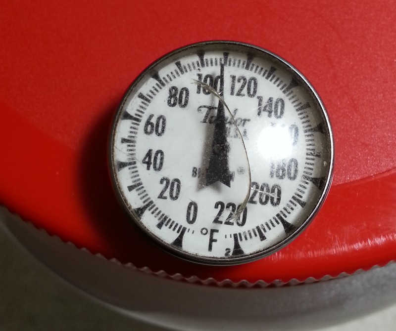
Monitor the water temperature. Getting it too hot could melt plastic, spew scalding water out the vent, etc. The one I built, with a half-gallon of water, can take 1kW for a couple minutes with only about 20°F rise. I added a dial thermometer. Actually, I got it hot enough once to distort the plastic jar, which I replaced (I eat lots of peanut butter). The water will temp stratify and get hottest at the top, so swirl the jar around between key-downs.
Make sure to include a little vent hole in the lid—even warming the water a little could build some pressure, and you don’t want the lid blowing off. I drilled a 1/16th-inch vent hole; large enough to vent but small enough to not spill much if tipped over.
If you use an SO-239 in the lid, be sure to caulk the inside connections with silicone caulk, to keep water vapor from migrating into the connector and coax.
Photos
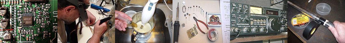
This is how I built it, using what I had on-hand. I didn’t have an SO-239 handy, but I did have a couple banana jacks, and that will also let me later add a capacitor and diode for a DC voltage measurement, which can be converted to peak RF power at about 1% accuracy, for calibrating my watt-meters. The jar is a plastic 64-oz peanut butter jar. I would not recommend using anything less than a half-gallon, as a smaller volume of water would heat up too fast. The wire is #12 solid copper, stripped from a scrap of house wiring.
Parts
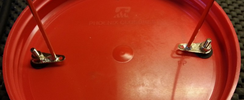
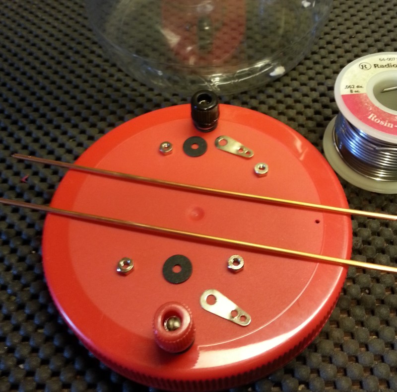
A little soldering (done before assembly).
A little more soldering.
![]()
I made a spacer out of plastic, to keep the wire spacing constant.
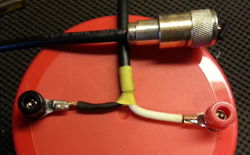
All hooked up and ready for water.
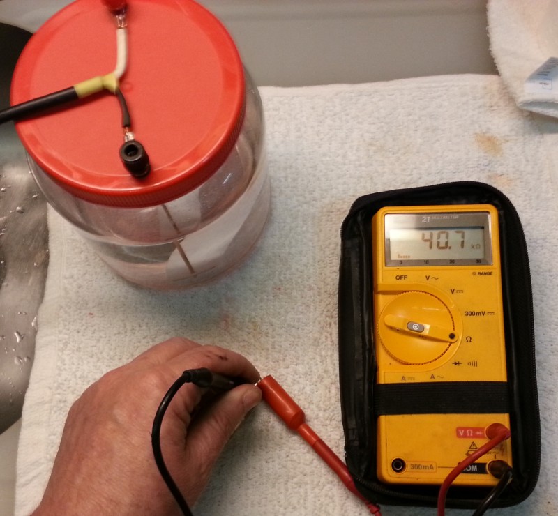
I thought to measure the resistance with an ohmmeter. At 9VDC, my tap water reads 40.7k, with the given electrode surface area and spacing. I kept adding salt, but it came down only to about 3.5k, and I realized the 9VDC ohmmeter wouldn’t represent the resistance of RF at several hundred volts. Plus, as I discovered later, there’s also some inductive coupling going on between the wires.
So I connected it to the tuner and re-did the water from scratch.
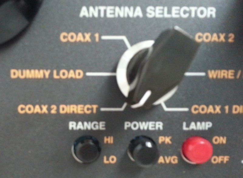
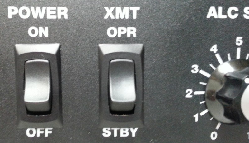
I used the Coax-2 Direct setting on the 989D. It’s conveniently close to Dummy Load position, which is the internal 300-watt resistive load.
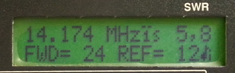
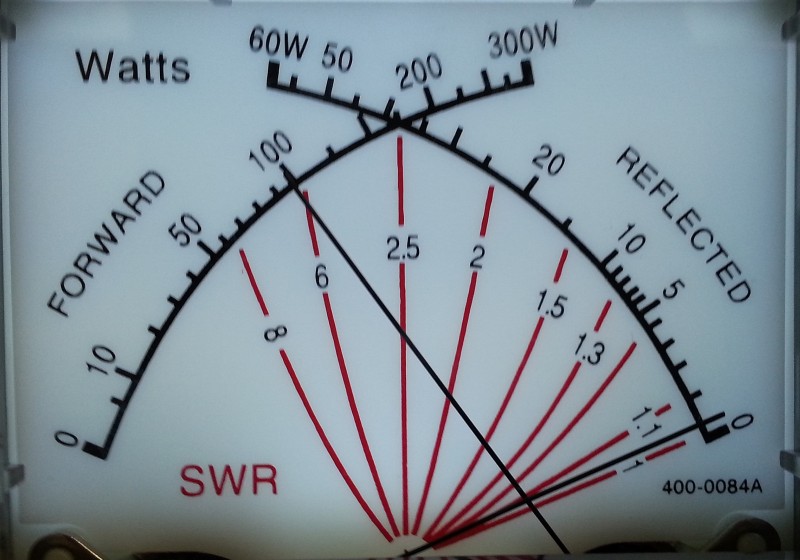
Here’s the SWR of my tap water at 20 meters, with 24 watts from the IC-7100. Note that it’s protection circuit is throttling the power back, as it should.
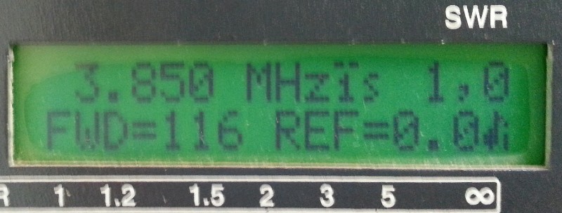
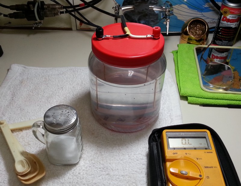
I couldn’t get the SWR below about 1.6 on 20, so I went to 80 meters and did the water over. It took a bit over 1/8th teaspoon of salt to bring it to 1.0:1.
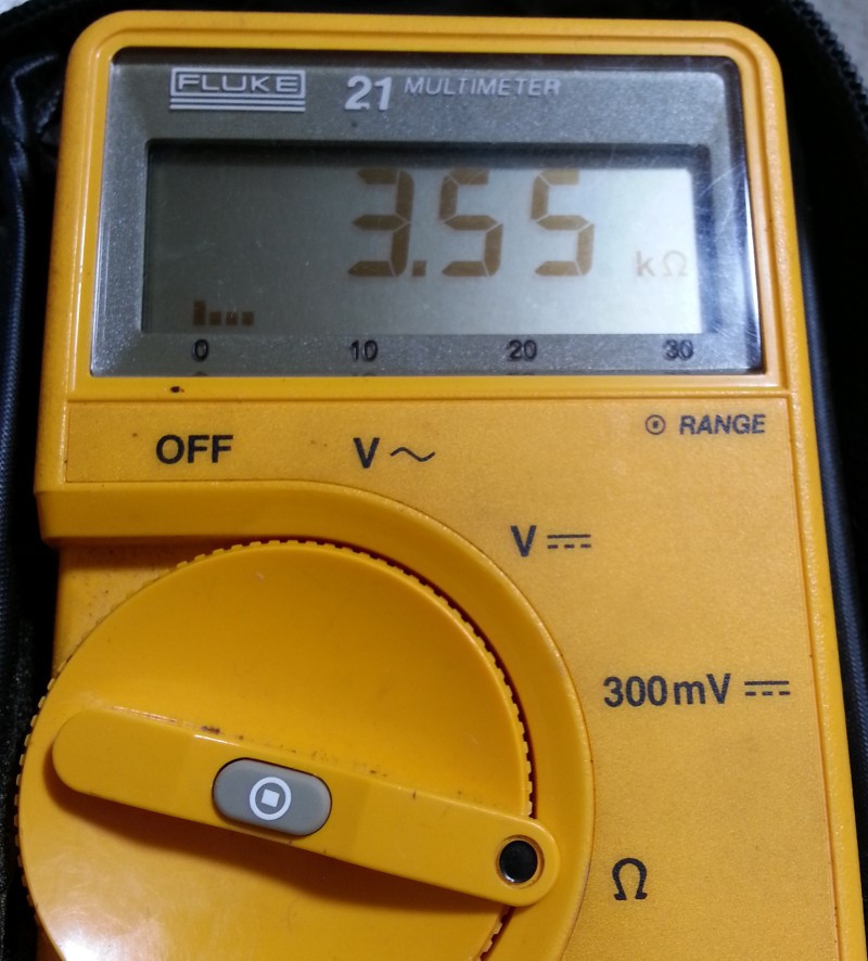
Just for reference, I measured the DC resistance. 3550 ohms.
How to adjust the salt: Is the resistance too high or to low? Easy! Unscrew the lid, transmit, and slowly lift the lid, thus raising the resistance. (Watch out for RF burns.) If the SWR goes up, you know the resistance was too high already and you need a bit more salt. But if the SWR dips, you know the resistance was too low, so you need to pour out some water and replace with fresh. It took me a half-hour or so to get it right. Make sure to stir well, after each addition of salt.
Okay! Now for some real power!
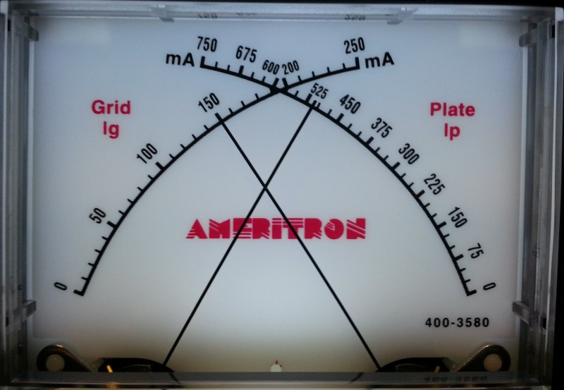
On a single 3-500Z, keep those high readings short! A few seconds at most. Watch the tube’s graphite anode glow; red is okay, orange is too hot.
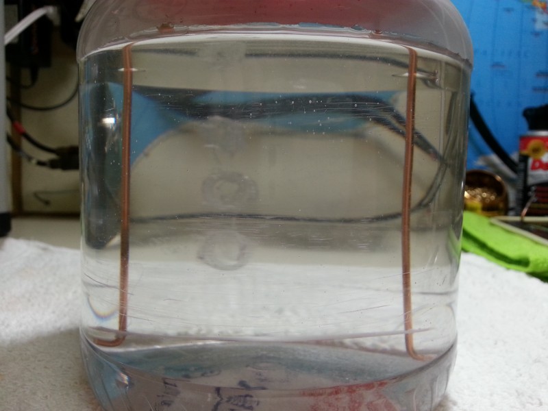
No bubbles. See? RF doesn’t make gas in salt water.
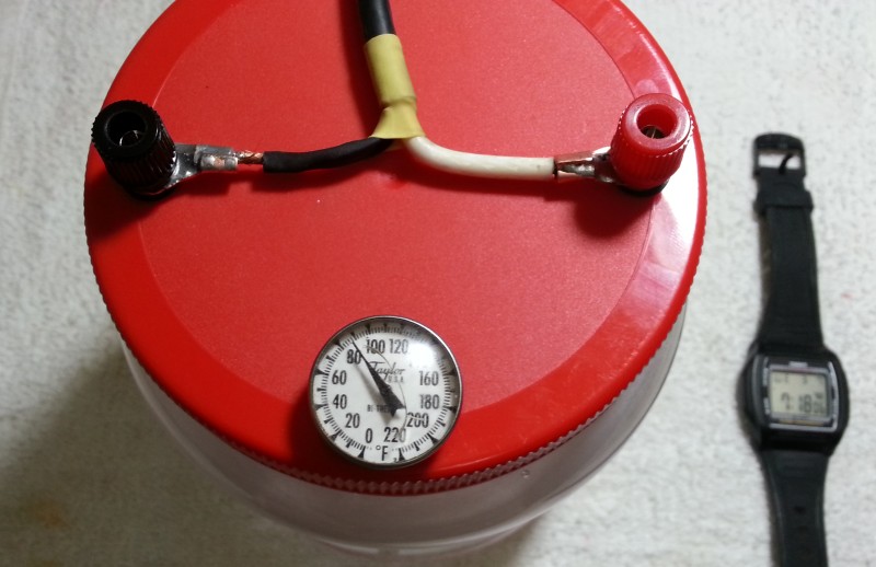
Okay, now for some duration tests. I drilled another hole in the lid and popped in a dial thermometer. Don’t touch it! It’s RF hot.
I did four intermittent 15-second key-downs at 500 watts, then a couple 15-second at 1,000 watts. I let the tube anode cool down for a minute or so between each. So, a minute at 500 and 30 seconds at 1,000 brought the water temperature up 20°F. More than enough time to tune up an amp! And no more on-air tests. Yay.
So, How Does It Work?
Power-wise, it does the job. It was easy to build and cost almost nothing. But frequency-wise, I’m not so happy. There’s something going on between those electrodes besides salt water resistance, probably inductive coupling. On 80 meters, it can be adjusted flat, but on higher bands it will only dip to 1.5 or so. Since I talk mostly on 80, I adjusted the salt water for that. For higher bands, I can completely flatten the SWR with the tuner, but that adds another step to the tune-up procedure. I’ll eventually do more experiments with different electrode spacings and shapes to see if that will flatten the SWR curve. Copper flashing or flattened tubing might be better than wire. Or worse. It might be that the electrode length needs to be reduced, and the water saltier, so there will be less inductive coupling. If anyone has built one with a nearly flat SWR curve from 160-10, please let me know in the comments.
| Band | SWR | Notes |
|---|---|---|
| 80 | 1.0:1 | Excellent |
| 40 | 1.1:1 | Okay |
| 20 | 1.8:1 | Lifting lid ~1" dips SWR to 1.6; R too low |
| 15 | 1.9:1 | Lifting lid ~2" dips SWR to 1.3, R too low |
| 10 | 1.7:1 | Lifting lid increases SWR; R already too high |
| 6 | 9.3:1 | Not usable |
Why does its SWR curve need to be flat? Because one would tune the antenna tuner to flat, with exciter power, then switch to a flat dummy load and tune up the amp, then back to antenna and talk. If you tune the amp to a 1.7:1 dummy load, then switch to a flat antenna, you’d have to tweak the amp again, on-air, defeating the purpose of using the dummy load in the first place. And if you flatten the dummy load with the tuner, then tune the amp, then you have to tune the tuner again, to the antenna. So having a flat dummy load eliminates one step of tuning the antenna tuner, or tweaking the amp on-air.
Note that I only needed to use the dummy load to determine max-power Load settings on the amp, which were recorded in a chart. In normal operation I just set the amp to the chart, do a very short (2-3 sec.) on-air to fine-peak the Plate, and talk. Since then (about a year now) I have not needed it, so I’m glad I didn’t spend a bunch of money on one.
Other Nifty Uses
Having a high-power 50-ohm dummy load is a good way to measure power, distortion, and audio quality without QRMing the ham bands or bothering people for uselessly subjective audio reports. If you have an RTL-SDR dongle running on the computer, it will pick up enough signal from the dummy load so you can transmit at full power and look at your signal on the spectrum and waterfall, and record your audio. This is a very handy and inexpensive way to check for splatter, signal purity, and audio characteristics such as equalization, compression, and background noise.
The old Heathkit Cantenna had a little circuit on top with a diode and capacitor that you could connect to a DC voltmeter and calculate power, with fairly high accuracy (1-2%), and then calibrate your watt-meter. There are several good articles on-line about that method, so I won’t repeat it here.
Another interesting thing to explore is calculating power very accurately using the calorimetric method. The dummy load will need an exact known volume of water (weigh empty and tare, then fill, on a digital gram scale), then be insulated in a small Styrofoam cooler, with an accurate lab-grade thermometer in the salt water protruding through the top. One then transmits for a certain length of time and records the temperature rise. (You’ll need to swirl it around because it stratifies.) From this, power may be calculated. Again, there are several articles on-line, so I won’t go into details here. Note that all lab-grade power calibration standards use the calorimetric method, so if you really want to reach for maximum accuracy, that’s the way to go.
Next, we’ll look at a couple of repairs I made to the MFJ-989D antenna tuner.
73, — KV5R
Thanks for doing this. The results are interesting.
I found most oil based dummy loads have resistors rated (in air) for about 20% of their claimed oil power capacity. I found a 200W unit on Amazon with a very flat SWR. It meets my needs for now and in the future I am considering putting it in oil. It’s too long for a 1 gal paint can but 1.5-2 gal should work fine.
Hi,
I built one from June 1965 QST Aqueous Dummy Load Alexander Marion W2CUE. Good SWR from 3 to 30 MHZ under 1.2:1. Used gallon salt water rather than 1/2 gallon lowers temperature rise in half. It uses S0239 with spacing of wires only small parts are exposed. see article. Built for a new ham to save money. At 1 MHZ SWR rises. You are right its NOT DC resistance its still thousands of ohms at low RF SWR. Formula of grams of salt in article works when multiplied by 3 for a gallon of water not much salt. Hope your right about corrosion won’t occur on regular copper wire been a few weeks,
Forgot to mention …. if it wasn’t for my TT Jupiter, I would call my 706MKII the best radio ever built.
“With AC, metal ions don’t migrate, they just jiggle to and fro.”
That is the ham radio quote of the decade! lol
Just in my humble opinion your electrodes are too far aprt and the Jar is too small.
With a 1 gallon pickle jar and 100% salt saturation ( meaning I add salt until it stops dissolving ) my electrodes are 1 1/2- 2″ apart with the ends about 2″ from the bottom of the jar.
Mostly flat SWR everywhere with and occasional wiggle on the higher bands.
Great article!
And I also used light bulbs in the good old days. I remember having a great 5X QSO on 80M from El Paso to the Big Bend National Park area, about 300 miles, with a Knight Kit T-60 and a 60 Watt bulb soldered to a few inches of coax.
But, my best “unusual antenna” QSOs were when I was station in Germany in the mid 60’s. My neighbor (Ham) took a trip to Tripoli, Libya and asked me to keep in touch with his Heath Kit HW-32 20 Meter monobander. Due to weather I couldn’t get an antenna up so I stripped back a length of coax and connected it between two large adjoining windows in my Army quarters. I had several great QSOs with him and later with many others on that side of the world.
The only problem I remember is that I couldn’t get the Italian stations to understand what a window screen is. 😱🤣😂🤣
Don, W5MML…🤠
Wow! Does this post bring back memories. When I was a kid, as most back then, I did not have much money. I built a lot of transmitters out of junk and army surplus. It did not take long to learn light bulbs radiate RF. We learned to make saltwater dummy loads. They work fine.
BTW we also used paper blind springs and old output transformers to make reverbs.
Ah, the good old days when we built things.
Great posts on the 7100. I have on on the way to replace my IC-706mkIIG that died.
Howdy Bill,
Yeah, good ol’ light bulbs… The early ones used a straight filament that zig-zagged up n down; later (and current) ones use a filament that’s double-coiled, and at RF is more an inductor than a resistor, so is useless as a dummy load.
I like building my antennas and station accessories when I can, not often anymore; getting hard to do anything. I tried one last time to fix my 706 the other day, which has that intermittent powering off problem for years. After this attempt, it won’t come on at all. I ran a #30 wire and bypassed the line from the processor to the transistor that brings up the little 12v relay, and nothing! Well, the ribbon cables in the 706 get old and start falling apart; I suspect that’s the issue. When it did power up, everything worked fine; I may either part it out, or enjoy throwing it in the burn barrel…
You’ll love the li’l 7100. It’s just so much better than a 706. I particularly like the DSP IF filters; set any width you want, with very steep skirts. And the computer connectivity, plug in USB cable, set up software, done.
You might like my panadapter page; add the RF tap shown, run it to a little SDR, set up HDSDR, and poof! waterfall on the big screen. Seeing the whole band at once is so nifty, you’ll wonder how you ever lived without it!
73, –kv5r
Let me know before you toss that 706 in the burn barrel. I’m always looking for donor units to keep my fleet running.
73,
— Zach
N0ZGO