using a solid-state relay…
© 2018 by KV5R. All Rights Reserved. Rev. 7/27/21
New! 7/21 I built a full breakout box for the 7100’s accessory jack. See below.
Introduction
So you got your nifty HF transceiver and now it’s time to move up to the big leagues and add some power to your signal. You order a nice amplifier, only to discover you also need an “interface” to connect the radio and the amp.
The problem is that there are no standards for connecting the keying circuits of transceivers and amplifiers. Each manufacturer uses their own voltage and current for this simple operation. Of course, radio manufacturers sell (very expensive) amps that will plug right in to their radios, but most hams opt for less expensive options. Other companies make amps that are much lower cost-per-watt, and just as good, but the keying circuit is generic, with interfaces provided at extra cost. The problem is that they cost too much! Why? Because they are built to be compatible with a wide range of radios and amplifiers, and thus have a high parts count. They are plug-n-play, so you don’t have to look up specs for your radio and amp or do any designing. If that’s your goal, then by all means buy one, but if you’d rather roll your own, please continue reading.
You can build an interface for $10-$30; all you need is an old stereo audio patch cable and a small relay. The audio cable is the typical stereo RCA phono plug cable, 3 to 6 feet as desired. Cut the phono plugs off one end and wire them to the radio’s accessory jack and relay. One cable (with relay) for amplifier keying, and the other (directly connected) for ALC. Most amplifiers use RCA phono jacks for both keying line and ALC line. At the radio end is the accessory plug that comes with most radios. Icoms come with an 8 or 13 pin DIN plug with pigtails (short wires), so you can look up the colors and connect to the wires without having to solder to the tiny pins in the DIN connector.
The relay is selected to comply with the needs of the radio; typically the coil is 12VDC at 10-20mA. Icom radios use a pin on the accessory jack called “HSEND” that when transmitting can sink 13.8V at 200mA to ground. (Some Icom models, like the 706, are limited to 20mA.) Most third-party amp’s keying circuits will overload it and blow the switching transistor in the radio. Also, a relay coil will need a very fast power diode across it to absorb the high-voltage pulse generated by the collapsing magnetic field in the coil when it is switched off. This pulse will greatly exceed the peak inverse voltage (PIV) rating of the radio’s switching transistor and POOF! — time for an expensive repair… The diode is connected across the relay coil reverse-biased, and the pulse (which is reverse-polarity) forward-biases it, causing it to conduct and absorb the pulse.
Mechanical relays have that nasty coil spike, switch relatively slowly, can get dirty contacts, and are noisy. They also require extra parts, such as a resistor (in-rush current-limiting), a capacitor (RF bypass), and the diode. A better solution is to use a solid-state relay. These typically have an LED, photo-detector, and power MOSFET encapsulated in a very small package. No other parts are needed, not even a perf board or enclosure. The device is small enough to simply “float” in the cord assembly. Prices are a little higher than comparable mechanical relays. The one I used is about $22 (plus shipping) from Mouser.com.
My Interface
Disclaimer: The author is not responsible for your mistakes. If you fry something, it’s your own fault! This article is intended for people that know how to look up specs, solder, and test simple electronic circuits.
With thanks to KK5DR, I discovered the Crydom DMO063 (Mouser p/n 558-DMO063), a solid-state relay (SSR) with an SPST-NO MOSFET switch rated at 60VDC at 3A. The input is 3-10VDC at 20mA (at 5V). It appears to work at 13.8 volts also, drawing 12mA. The switch-on time is an incredibly fast 50μsec. See the datasheet for all the details. I built the following isolated solid-state keying interface according to KK5DR’s article. It also shows how to build one using a mechanical relay.
My radio is an IC-7100 and the amp is an AL-80B. The 7100’s HSEND line can sink 200mA, and the AL-80’s RLY jack supplies 12VDC (through the coil) and when grounded draws 100mA, so it looks like they could be directly connected—but wait! Each side supplies its own voltage source and ground. A direct connection would mean that HSEND closure would be sinking the amp’s 12V to the radio’s ground, and yes, their grounds are connected, but I don’t want to risk it, so I built the isolated interface so each side can sink its own power to its own ground. It’s just better to load the radio with the SSR’s 12mA, not the amp’s 100mA. And it’s also safer that way, particularly when considering that amplifier relays can fail and arc RF to the coil of the relay, which will surely fry a directly-connected radio! Isolation is a very good thing.
Update September 2019 — Bill, KO4NR (see comment below) found a better solid-state relay for this application, particularly the TS-850 and others that have a 10ma amplifier keying output. It is the Crydom MPDCD3 for DC output switching (up to 60VDC at 3 amps), or for old amps with line-voltage keying relays, look at the AC versions (MP120D3 MP240D3 MP240D4) in the same Crydom MP Series Datasheet. $25.80 at Mouser (watch out, other places sell it for ~$50 with a DIN rail mount).
Bill verified with tech support that the MPDCD3, which is rated to pull 23ma at 32VDC on the input, pulls 8ma at 12V. And since the minimum turn-on voltage is 3VDC, I suggest that the input might be connected with a series resistor to drop the voltage and current even further. So don't get get the DMO063 I used, rather get the MPDCD3 for amps with DC keying, or the MP240D3 for amps with line voltage AC relays.
All these devices are optically isolated and much safer to use than bipolar transistors, which if they fail to base will put amplifier relay coil power into the radio and damage its teeny SMT amp keying output. (end of update)
Photos
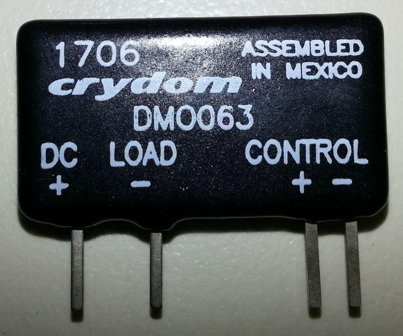
Crydom DMO063 solid-state DC-DC Relay, $22. Note that part number is DM "oh zero" 63. (Use the MPDCD3 instead.)
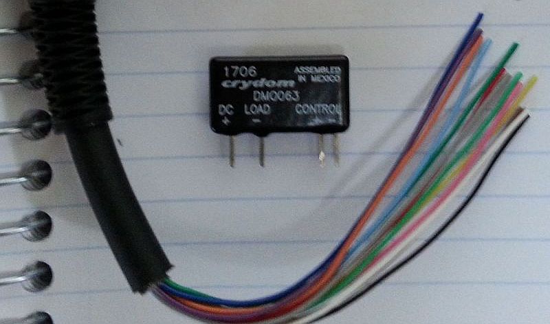
I used the 13-pin DIN accessory pigtail that came with the IC-7100.
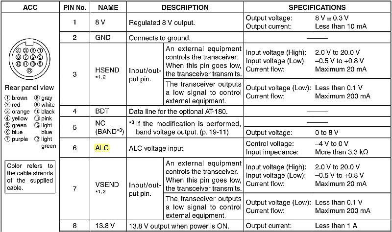
Part of IC-7100 manual for 13-pin ACC. Pin numbers and pigtail colors are the same for the 703, 706, 718, 7000, and 7100. Other Icoms use an 8-pin DIN Acc. Refer to your manual.
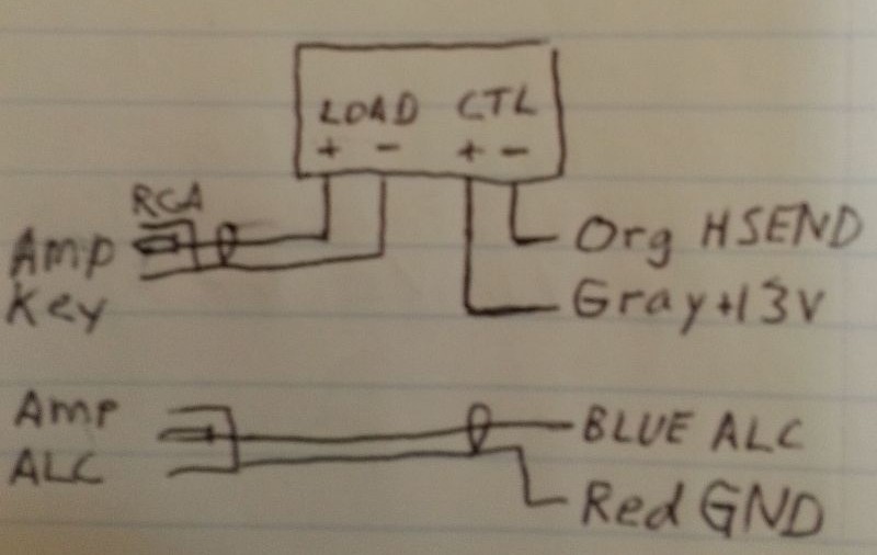
Make a little sketch to plan your soldering. Yes, red is ground. Nobody knows why…
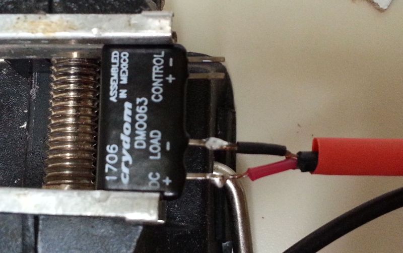
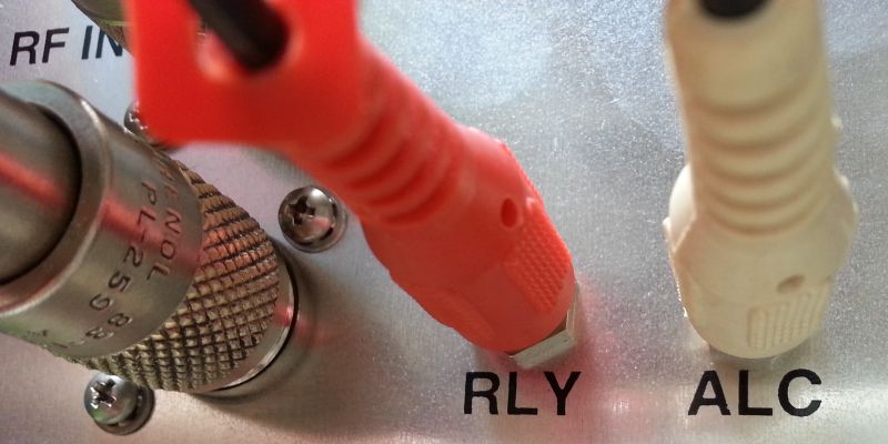
First, connect the red phono-plug cord to the SSR’s output. Obviously, the center is + and the shield is - .
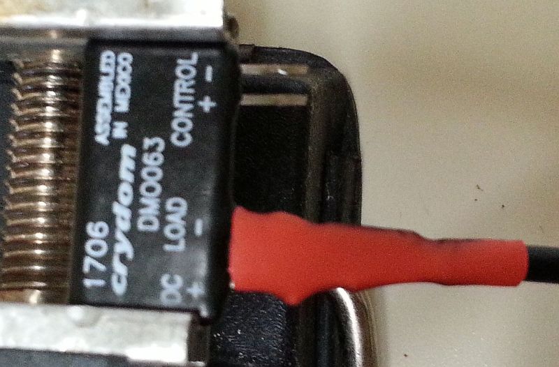
Dress everything up with heat-shrink tubing.
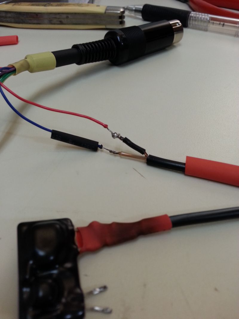
Connect the other phono plug cord to the ACC plug’s ALC and ground lines. Heat-shrink it.
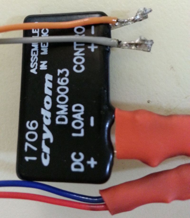
Connect ACC plug’s 13.8V line to CONTROL+, and the HSEND line to CONTROL-. heat-shrink them. NOTE: If these short, it will blow the transistor in the radio! Make sure to insulate them well. (Please ignore my nasty soldering, it wasn’t a good day to solder…)
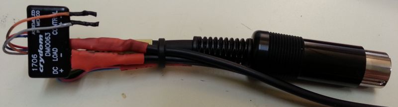
Fold the cables back to the jacket of the ACC plug with a cable tie, to provide a strain-relief.
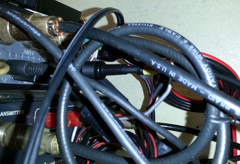
Plug it in. Notice how the little device is lost in the maze. We don’t need no stinkin’ little box!
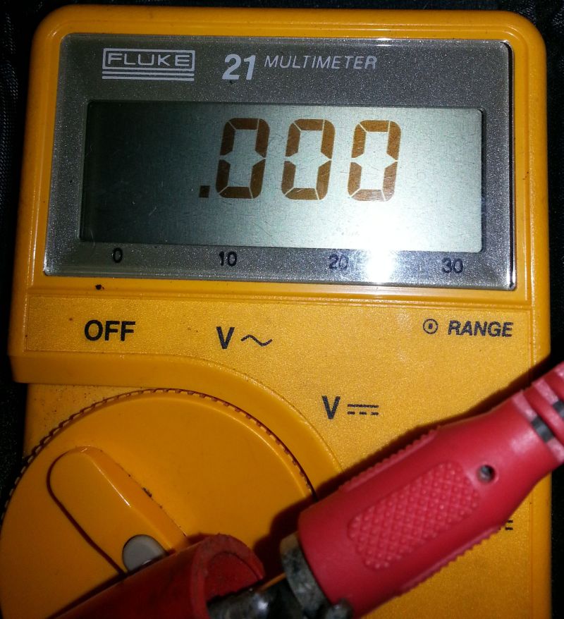
Test it by connecting an Ohm meter to the red phono plug. Key the radio. TA-DAAAA! It works.
Connect to amplifier
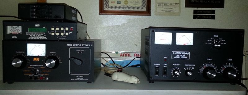
Everything working fine!
Notes
This SSR device (DMO063) is not suitable for old amps that use AC, or DC above 60 volts, for its t/r relay. The DMO063 is 60 volts max, DC only. Use a suitable relay for those. See your amp’s manual to verify its keying voltage and current. See 2019 Update, above, and use the MPDCD3 for DC relay amps and the MP240D3 for AC relay amps (unverified, but should work fine).
I suggest using a series resistor on the input that's low enough to trigger the SSR (3V minimum), but high enough to limit the current to 10ma if the internal LED fails shorted. Yes, the Crydom SSRs have internal resistors, but more wouldn't hurt, particularly if using a radio with a 10ma keying output.
If you get erratic behavior from either amp keying or ALC, wind the cords a few times through a FT-140-77 (low HF bands), or -31 (high HF bands) toroid from Amidon or Palomar. (Snap-on split chokes are crap).
Make sure to cable-tie (or tape) the phono cords back to the ACC plug to prevent pulling on the connections. Make sure all connections are properly soldered and well insulated.
Make sure to set a 15-30 millisecond TX DELAY in the radio. This gives the amp time to close its big open-frame relay before receiving RF drive. Failure to set TX DELAY may result in popping sounds when using VOX, and "hot-switching" may damage the amplifier. In the IC-7100, TX DELAY is in the Set → Functions menu.
2021 Update: KV5R's Accessory Breakout Box
I started playing around with separate receive antennas, such as the Loop-on-Ground (LoG), and needed a way to run a seperate receive antenna on the 7100, which unlike the larger radios does not have a receive antenna input. Since the SSR was keying the amp, I couldn’t use the HSEND line for other purposes, like antenna switching. So I built an accessory breakout box. It adds more functionality to the HSEND signal than just keying an amp.
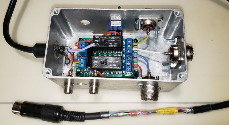
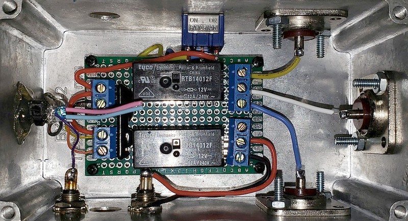
The Crydom SSR now drives a pair of Potter & Brumfield RTB14012F relays, one for antenna switching and one for amp keying. Their contacts are rated at 12 amps at 240 volts. The RTB14012F is a very good general-purpose relay for RF antenna switching, and is the same one used in the W8ZR StationPro. I read somewhere that W8JI tested dozens of GP relays at RF QRO and found them to be the best GP relays for the purpose. And at ony $4 each, they are definately better than megabux RF coaxial relays! For the cable, I used an old VGA monitor cable, which has 5 wires and 4 tiny coaxes inside, and is well shielded. It even has a ferrite choke on it. I spliced it to the Icom 13-pin DIN accessory pigtail.
The RTB relay is overkill for keying an amp (typ. 12v @ 100ma), but I got two of them in the ebay deal. An RY12W-K small signal relay, which has contacts rated at 24V@1A would be fine for keying an amp.
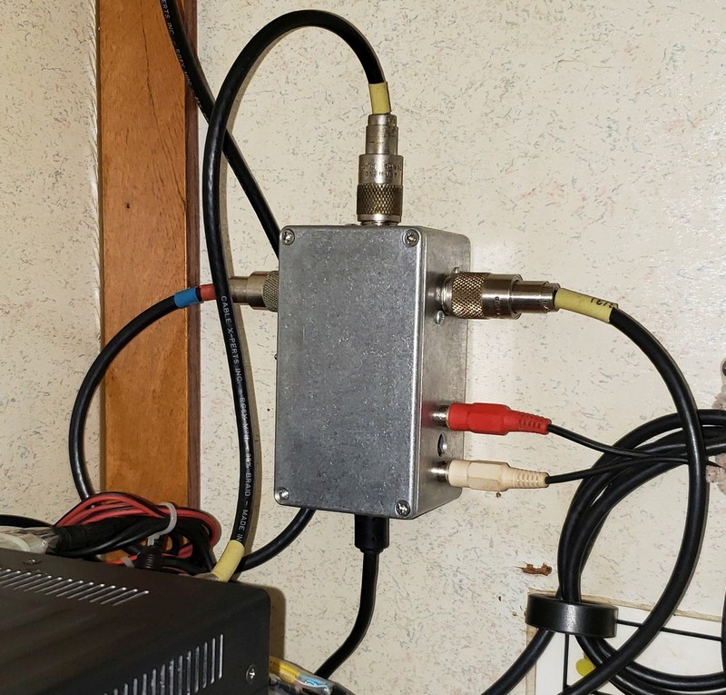
Since the Bud cast aluminum box I had has stuff coming out all four sides, I just drilled a couple holes and screwed it to the fall behind the radio. It would be better to put all the connectors on one side of the box; I had this box already drilled for another project.
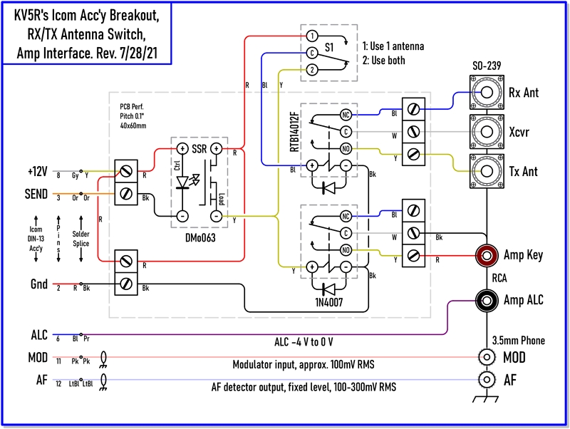
After building it (with considerable head-scratching), I fired up QCAD and made a nice schematic, laid out as a wiring diagram. Note that the switch powers the antenna relay ON all the time when in the single antenna configuration. Switched the other way, the SSR operates it, for separate receive antenna operation. If you would like to print the schematic, you can download the pdf here.
Notes:
The RTB relays do not appear to have internal flyback suppression diodes, so I added 1N4007’s to the coils. They are rated at 1000V@1A. Be sure to connect them backwards! The banded end goes to the + side, so they only conduct when the relay opens and the magnetic field collapses, absorbing the reverse voltage spike.
If you don’t want to build your own relay board, look at the HiLetgo modules on Amazon or Ebay. For example, https://www.amazon.com/dp/B00LW15F42/ . Those have buffer transistors running SRD-12VDC-SL-C relays, which appear to have 10 amp contacts, and 30ma coils.
The box is powered by the +12V line from the radio’s accessory jack, which has a limit of 1 amp. If you add more relays, remove the jumper on the board’s input side and provide a separate 12v power source to the Load side of the SSR, and thus, the relay coils.
Adding more accessory relays is easy. I may add one of the HiLetgo modules, and a couple SMA jacks, to disconnect and ground the input to my SDRPlay receiver during transmit. One might also add an "ON AIR" sign, a 12v fan, or something else; anything you need to happen when you push the PTT.
The antenna relay is placed inline with the radio, before any tuners or amps. That way the receive antenna is untuned, since the LoG I am using is broadband, and the transmit antenna’s tuner settings would be all wrong for the receive antenna.
Next, let’s save another $75 and build a good old-fashioned salt-water dummy load!
— KV5R
Thanks for the great article!
I had previously built a unit so my Kenwood TS-180s could trigger the Yaesu FL-2100b but it was destroyed in transit.
I wonder if you provide this kit or “preferably” pre-constructed as I love Amateur Radio but suffer from many physical problems and am on a disability pension?
Thank you for any help you could please provide, kind regards Noel VK4…
Greetings Noel,
I really wish I could help you but I’m in a similar situation. Disabled, and went almost blind last March.
A basic SSR interface is just the module and an RCA cable and maybe 4-6 solder points, which could be just crimped butt-splices.
Or you can get little hoddy relays modules (“Hiletgo”, etc) on Amazon, with screw terminals, no soldering or crimping!
Might try the local ham club, or a ham that sells assembled kits for reasonable cost.
Vy 73, kv5r
Hi I have an Icom IC-551D 6 meter Transceiver. It outputs 8 volt at 4 milliamps very little power! is there a chance for a solid state relay to work or would this require a transistor switch of some sort to provide ground to a modern Linear amplifier. I am thinking an Arduino relay at 4 volts might possibly work but not really sure. I am moderately Handicapped with severe tremors but I will try with help from someone. Cheers 73 Mike vk4sy
So i just found this site, i ordered all the required and will be putting together in a few days. My question, probably stupid, do you connect just the orange/gray to relay and all other wires are NOT connected? Is this correct??
For an amp, four wires: 12v, Gnd, Send, and ALC.
Others might be used as needed, for VSend, RTTY, audio in/out, etc.
I found that I can use Pin 2 and 4 on the 7 pin DIN for keying with my Kenwood TS850S. Check page 17 in the Operating manual. The relay in the 850 (K3) is rated for 3A and up to 30vdc. No need to use an SSR or transistor.
The SSR does work however but no need for additional hardware and potential problems.
Be very, very careful about using the 12vdc 10ma provided on the DIN Pin #7. I fried my RF board when the transistor failed. The relay however is not connected to the radio’s circuity for amp keying.
73,
Bill KO4NR
W8JI warns that the FL-2100b can spike to -100v at relay closure (much more if the tubes arc). That said, I’m wondering if something even more robust might provide some headroom What do you think about a “CG Solid State Relay SSR-25DD DC to DC Input 3-32VDC Output 5-240VDC 25A Single Phase” (similar to a Crydom) but designed for appliance applications)? Or am I worrying too much? Thanks, KD4E
I was told elsewhere that these relays all have a reverse connected diode across them to quench any back emf when the relay releases, so my concerns unfounded. Question: Are you recommending the Crydom MPDCD3 for an Icom IC-7100 to Yaesu FL-2100b, rather than the Crydom DM0063? Thanks
Howdy David,
Not sure what Tom means about the 2100 spiking to -100 VDC on relay closure. When a relay coil is energized there is no voltage spike, only when it opens and the field collapses, and that is much more than 100V. That’s why any DC-coil relay needs a reverse “quench” diode across the coil. If it doesn’t have one, just add one. Any ol’ axial-lead power diode like 5-10 amp and 1000 PIV should do nicely. You could put it (in reverse polarity) right across the terminals on the back of the amp. But surely it already has one in the amp, right across the relay’s coil.
Either the DMO063 or MPDCD3 should work fine. Prefer the MP for radios with very low (10ma) amp switching outputs, as the MP’s input current is lower than the DMO. The output ratings seem to be the same, max 60V at 3A. Other SSRs with higher voltage rating would be even better.
An important consideration is the SSR’s input to output (I/O) isolation voltage rating. If the amp arcs its relay and puts 3-6 kV on the input line, you want to blow the SSR’s output, not the radio. The DMO and MPD, for example, are optically isolated, with several kV I/O isolation. Hams who use a tiny little relay, or transistor switch, don’t realize that a high-voltage arc at the amp’s big relay will surely arc the much smaller control relay, or blow right across a transistor switch.
So, the design considerations are:
1. Input current (typ. at 8-12VDC)
2. Output current & voltage (to exceed the amp relay coil)
3. I/O isolation (in case of HV arcs).
There are some comments below on the 2100.
73, –kv5r
Excellent!
Waiting for caps and Harbach boards to re-cap the 2100 – will deal with the relay mounting and wiring at the same time.
Thanks for the help,
David KD4E
Hello, I am a user of an Icom IC746 and I need to connect it to a Yaesu FL 2100Z linear amplifier. I work digital modes so I need the switching to be safe and have no delay
Thank you
Dan LU4EN
Scroll down thru the comments, there’s 2 questions & answers on the FL-2100Z, should be same for your 746.
73, –kv5r
I just bought one of these SSRs:
https://www.ebay.com/itm/25A-240V-SSR-Solid-State-Relay-LIRRD-LRSSR-DA-3-32VDC-Trigger/133437056579
and wondered how best to provide the 12V (or lower voltage) to complete the circuit to the input so when the 7300 SEND line grounds the center RCA jack conductor to make a nice package. Maybe the above won’t work but it is my first SSR and I can find other applications for it.
The datasheet can be found here:
https://www.lirrd.com/products/dc-to-ac-solid-state-relay?variant=31483522220106
and it’s the LIRRD LRSSR-DA, one of the ones with a 3-32V control voltage and 3-35 ma control current and 10 ms on/off time. It can handle a fairly high load voltage also.
The 7300 Advanced Manual p.18-4 says the Send jack will sink <16V <0.5A, so it should directly key most any modern amp. For example, Ameritron amps key with 12V at ~100ma.
Of course, isolation is always a good idea. Just supply the Trigger + to the SSR from any handy 12V+. Might be a good idea to put a 100-250ma fuse inline with it just to protect the radio's amp keying circuit in case the SSR's input were to short (highly unlikely). Then connect the amp's keying line across the output.
Please let us know how it works out for you! Those are a LOT cheaper than the Crydom units at Mouser.
73, –KV5R
The Crydom unit you originally used is available used on eBay for about $15 including shipping. They are apparently pulled from equipment taken out of service.
It may be a wile before I set this up, but I appreciated your article to point me in the right direction.
Mouser have the DMO063 for $24, can also get them from Amazon for $33 with free shipping.
GREAT ARTICLE!! I’m wondering if you are still using the DMO063 or did you swap it out for the MPDCD3. I just picked up a pristine FL2100z and will use my ic-7300 with it I was going to use a mechanical relay until I saw this article. The FL2100Z uses 12 volts, on the relay but I’m not sure yet about the current draw.
I ordered the DMO063 before I read your whole article and am wondering if I should get the MPDCD3 or just use the DMO063.
Are you still using the DMO063 or did you change it out.. Sorry for the long dissertation here! Thanks in advance..
Howdy Terry, sorry for the long delay, I somehow missed your comment.
I still use the DMO063 on my 7100. Your 7300 has the SEND jack that will sink up to 500ma, and will probably key the FL2100 directly, but using an SSR for isolation is a good idea. The 063 pulls way below the SEND jack’s limit. The reason I mentioned the MPDCD3 is for people with radios with send circuit limited to like 10-20ma.
73, –KV5R
Can I do this using the RCA send Jack on my 7300 with a RCA cable?
Yes, I would think so. Look at your manual and see what’s the switching and current capacity of the send jack. If it’s like the HSEND pin on acc’y jack, probably be something like, TX closes 12V to ground, at up to 100ma, maybe 200.
If the send jack will operate a small relay, it’ll certainly operate the Crydom SSR, at just a few milliamps input.
73, –kv5r
Thanks
I love this solution. I have been searching for info on making a cable that works between an Icom 745, and an FL1200b. Only thing I can’t figure out is the gnd of the relay to which pin on acc jack. Any thoughts would be helpful. 73, Art. VE7ER
Icom- http://www.radiomanual.info/schemi/ICOM_HF/IC-745_serv.pdf
FL1200b- file:///C:/Users/Asus%20T100TA/Downloads/FL-2100B%20AMP%20Operators%20Manual.pdf
The Icom manual you linked says on page 3-14, section 3-11-6, that the radio has an internal relay on the SEND jack, so you don’t need an interface, or the Acc’y jack. Hopefully, the internal relay in the radio simply closes to ground, and the FL2100B wants KY to E closed for keying. I’d test both with multi-meter before making a direct connection.
–kv5r
Yes my thought was to try and pull the GND of that “Send” jack, but as I’m not using an Icom linear, everything I have read is that the Yaesu will demand more from that inboard relay as far as milliamps, than it can maintain. I am however stoked to see a solid state relay option on your page here. Thanks for the reply, and I will update you when it’s up and operational. 73, Art VE7ER
I’m taking a cue from you and doing the same interface for my Kenwood TS-850. The interface I was using failed and the RF Board in the radio was severely damaged. This is a link to that interface. It worked well for 14 years then Bang!!
https://www.qsl.net/k0bx/amp.html
I had to use a different Solid Stare relay because the 850 supplies 12vdc at 10ma out maximum (Pin 7). Took a while to find a suitable relay but I did. Here is the datasheet for it.
It is part number- MPDCD3
http://www.crydom.com/en/products/catalog/mp-series-ac-pcb-mount.pdf
Their Tech. Support confirmed that at 12vdc the control current is 8ma.
73,
Bill KO4NR
Howdy Bill,
You put the same link twice so I looked up the part number and got the datasheet link and fixed it for you.
Looking at the datasheet, that would be a better SSR than the one I used for amp interfacing. It says “Typical Input Current @ 32VDC” is 23 ma, but the minimum turn-on voltage is 3 VDC, so you don’t even need 12V, you could series-resistor the input down to say 5V and it’d probably be way under 10ma. After all, it’s just turning on a tiny LED in there to trigger the device. Come to think of it, a resistor on the input would also protect the radio if the LED ever shorted. The DMO063 I used says it pulls 20ma at 5V, and at 12 volts I donno. I should probably put a series resistor in mine, too.
I see Crydom also has a couple that handle AC output up to 280VAC at 4 amps (MP240D4), that would likely handle old amps with big ol’ 120VAC relays quite nicely.
Yeah, the old one you were using looks great, but then the bipolar transistor fails to base, and POOF! amp relay coil power into your radio. Optical isolation is so much safer.
I’ll edit the article to include your findings. Thanks!
73, –kv5r