
© 2002-2011 by Harold Melton, KV5R. All Rights Reserved.
Shop for 2 Meter Antennas here.
A Popular Project
Lots of people are building this antenna! One fellow even improved upon it by making the elements out of aluminum - inside a ¾″ PVC pipe — see QST August 06.
Antennas just cost way too much! You can build this one for well under $10. It’s a:
- cheap,
- easy,
- stealthy,
- good performing,
- no ground plane,
- portable/mobile/marine/base,
- fun project antenna!
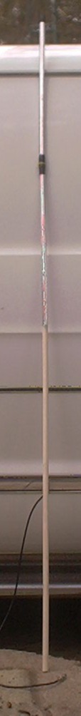
This is an off-center-fed sleeve dipole, made of ½″ CPVC and aluminum foil tape. The elements are fed 3-¼ inches below center, with the coax inside. Off-center feed is required because of the interaction of the lower element with the coax inside. Note: if you make it center-fed, the SWR will be about 2.5:1 across the band. Lowering the feedpoint by 3-¼ inches lowers the SWR to under 1.5:1. It is very broadband, being useable from about 142 to 152, and all of the 440 band as a 3/2 dipole. Also works quite well as a VHF/UHF public service band scanner antenna.
Note: I do not claim origination of this general design. OFC sleeve dipoles have long been used as marine HF antennas, and more recently, are widely used in small UHF wireless consumer devices.
This dipole was constructed as follows.
- Cut 7 feet of ½″ CPVC.
- Drill 7/32nds holes at 22-¼ and 58 inches from the “top” of the CPVC pipe.
- Cut upper element tape (2" wide aluminum duct tape) at 22-1/8th inches. Make two.
- Cut lower element tape at 15-5/8ths inches. Make two.
- Apply two overlapped layers of the tape to the upper and lower parts of the CPVC, leaving a ¼ inch gap at the hole which is 22-¼ from the top. The overall length of the two elements should be 38 inches.
- Take 6-12 feet (or as needed) of RG-58 and apply the appropriate connector to one end.
- Strip about an inch of the other end; fold the shield back. Bend a curl in the end of the center conductor.
- Push the coax into the lower hole with the curl “up” and guide it into the pipe, pushing and twisting as needed, until it pops out of the upper hole, between the elements.
- Strip out about 5/8ths inch of the center conductor. Apply a little Penetrox to both center and shield.
- Pull the coax back until just the conductors exit the hole.
- Lay the greased conductors on the elements and tape them down with a couple little strips of aluminum tape.
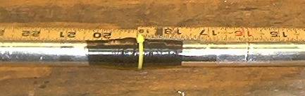
- Tape the whole feed with several layers of tightly-stretched electrical tape (Scotch 33+). Secure the end of the tape with small cable ties.
- Seal the ends to keep out water and bugs.
To make it look cool, spray paint it glossy white, dry, then spray every other six inches with flourescent orange (portable or bicycle); or olive drab (“covert” ops). I painted mine white because that’s what I had handy. Don’t use conductive (metallic) paint!
The same idea (CPVC and foil tape) may be employed to build small yagi antennas also.
Ignore the ruler — it should read 22-¼ (from the top), not 19 (photos taken on first try).
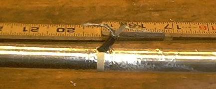
The coax conductors are connected to the tape elements by being (1) greased, (2) sandwiched between aluminum tape, and (3) compressed with several layers of tightly-stretched electrical tape. Again, ignore the ruler — it should read 22-¼, not 19. Make sure to use conductive grease (Penetrox) and lots of pressure at the feedpoint, to ensure that it can handle moderate current.
The antenna can be stuck down the back of the shirt, carried, or easily mounted on bicycles, etc. With a little more weatherproofing, it will make a fine dual-band base station antenna of moderate gain (2.2 dbi) and stealthy appearance (paint it the same color as your roof then clamp it to a vent pipe).
How Does it Work?
Fabulously! The ½-wave dipole, even quite near the body (which you can use as a reflector if needed), works so much better than the H-T’s duck - there’s just no comparison. With the six-watt H-T on a full 12.7 volt, 7AH lead-acid battery, and the dipole, it performs as well as a mobile of the same power. I can walk around with this rig and hit several repeaters 20-30 miles away with ease with 4 watts - and even get full quieting into a repeater 9 miles away on ½ watt!
August 2006 Update
Since the QST article, many people have written emails to me regarding this design. Several are building variations of it, and we are compiling more data, which will be included in this article.
Notes:
Many people asked me for a formula for the offset. I don’t have one. The antenna described herein has the feed point about 8.5% below center. This will vary with the coax and PVC used.
How to determine the offset: Build one with the foil tape elements a few inches too short. Wrap aluminum foil around the ends, with rubber bands. Move the foil ends up and down till the SWR comes into line. Measure. Peel off the tapes and apply new ones, cut to the proper length. Test it a final time and if ok, seal the feed. That’s how I did it.
Don’t use gray PVC. It just won’t work - something about the plastic.
—73, KV5R
This looks to work on the same principles, but might be easier to waterproof. Interesting optimisation done in software.
Gathering up the materials! Just need to get some RG58. Maybe RG9 would be better for both frequncies. What is the idea behind having two pieces of tape per section? I’m coming up on the antenna chapter studying for my general ticket so I imagine it has either something to do with reception or ease of wrapping?
I have built a variation using 3/4 inch copper pipe that fits inside a PVC pipe. I use .7inch drip line inside the copper to act as a spacer insulator and to wind the coax coil on (using RG58 solid dielectric). Covers 135 to 170MHz with moderate SWR peaks. I like that is has nothing sticking out the sides. Easier to hide and transport
I made an antenna based on this using 1″ aluminum tubing with a Delrin insulator between elements. I have some tuning to do but after putting it together I get a 1:3 SWR so hopefully a little tweaking will get it down a bit.
Between this design and others, it does not seem to matter whether we use 1/2″, 3/4″ or 1″ pvc as long as the length of aluminum tape strips are accurate. Or does it? Does radius play a factor?
The aluminum tape that I have been able to find is 1.89″ wide (1 15/16″).
Much like KV0PVO, I plan on using this antenna as a starter to play around with for my UV5R HT. I am brand new to the game.
Yes it does. As the diameter increases (i.e., l/d ratio decreases), the elements get a little shorter. Also, usable bandwidth increases. This is true of any resonant antenna.
A larger diameter will have a little less coupling with the shield inside the lower element, so the offset point will move a little bit.
Each one’s an experiment!
73, –kv5r
Wow!! Thanks for the quick reply!! I have a stick of 3/4″ schedule 40 PVC and plan on trying it. I will let you know how it turns out.
I built this antenna and have tested it by communicating via a repeater on Santiago Peak (Orange County CA) which is about 18 miles away according to Google Earth. I used about 32 feet of RG58 cable and SO-239 to SMA adapter connected to a Baofeng UV5R hand held. The top of the antenna is about 17 feet off of the ground between two houses. I hope to elevate it more with less blockage. Now that I have tested it, I will likely paint it during relocation.I
Thanks for the idea and feedback.
KM6RSZ
I built several of these antennas when in Florida and Alabama, 1990 -2008. I used RG58 and RG8X. I also used baking heavy duty aluminum foil rather than aluminum tape. Fantastic performance. While in Ecuador 2009 to 2016 I made several using RG6U as it was the only coax readily available. Had to make the offset slightly longer.
I made 6 meter and HF 20 to 10 meter verticals similarly using PVC pipe and aluminum foil.
For 17 meters experiment I made a 2 element beam similarly. It also worked well. I had 10 feet of PVC each side of center covered with 9 feet of foil. A small coil on the end 1 foot plus a dangling wire to tune it. The coil info can be calculated by one of several online calculators for shortened antennas.
comment is about how much power this antenna design will hold. would it hold 50 watts if it was built with heavier duty compnents.
The one I built for this article handled 50 watts. Used it for several years. Of course, if you built one using aluminum tubing, it would no doubt handle much more.
Tip: an old-school beach umbrella or similar frame, being metallic or composite wound with conductor material I find, makes an awesome stand and ground plane. Just invert the umbrella downward and use the guide hole in center for antenna. Might take a little creativity for finishing touches. Recycling is awesome !
Hi I made one of these antennas to convert a Baofeng UV5R into a base station. I had a stick of 3/4″ white PVC. It resides on top of my television antenna. I hooked up with used RG6 generic coax with a 3′ jumper to match the Baofeng. I can get out to a repeater 18.7 miles away with a good signal on 1 watt.
No tuning has been attempted yet.
Hi;
The reason that gray PVC give everyone such grief is that it has a very slow propagation speed and so the VF when it couples to the COAX changes very drastically. We were working with it doing some 2.4 gHz work and if I remember correctly had to use a VF somewhere around .35 maybe? Makes for a really short half wave antenna though.
That is correct, this is a great antenna, it is dual band and can also work the GMRS frequencies with a little fine tuning. Easy to build and light weight, hang itfrom a tree and have fun.
I built this antenna following your plans about 7 years ago and it worked well at the time and still does. I used it first as my base antenna but change it to a super J-pole which works a little better. but I like it and use it as a portable antenna for a hand held that I have.
I built mine ~2002 and used it ~10 years, it crapped out once because the wrinkles in the tape corroded through; re-taped it and spray-painted..
Now using a Tram discone feeding an RTL-SDR USB dongle, with SDR-Sharp. 80-1800 MHz. FunFun.