
© 2003-2011 by Harold Melton, KV5R. All Rights Reserved. Rev.06/11/05
Icom 706MkIIG Frequency Calibration
Unlike older radios, the 706 uses only one crystal oscillator (called the Master Oscillator). All other frequencies in the radio (L.O., 3-4 I.F. stages, VFO, and CW-offset) are computer-derived from the Master Oscillator. This makes it relatively simple to frequency-align the radio, so that it agrees with the Frequency Display in all modes.
NOTE! Various 706 models use different parts to calibrate the Master Oscillator. Refer to your Instruction Manual. Additionally, the lower diagram on page 63 (11: Internal Views) in my Instruction Manual is wrong:
- In the position shown as R602 is a trimmer capacitor (coarse adjustment), and
- Just above it is R602, the variable resistor (fine adjustment), and
- Adjustment of L623 is not necessary.
It is possible, if you are very careful, to calibrate the radio to +-1 Hz at 15 or 20 MHz (WWV as reference). Use the highest WWV frequency you can receive, usually 20 MHz in the middle of the day. Note: This is not the procedure used by Icon and the Service Manual. I consider this procedure more accurate because it uses WWV directly, bypassing the possible error of the Service Monitor, which is supposedly calibrated to WWV.
This procedure only applies to radios without the optional TXCO (high-stability unit CR-282). Also, this procedure is only for radios like mine — having a trimmer cap and a VR nearly under the 60 MHz gray coax in the lower (front) right-hand (radio inverted) corner. These lie just to the right of the encased (shielded) master oscillator.
You will need:
- #1 Phillips screwdriver;
- Jeweler’s Screwdriver set;
- 3.5 X headband magnifier and a bright light;
- Air Conditioner and/or heater, and digital thermometer to control room temperature;
- And for greatest precision, a computer running MixW in the PSK mode — read the audio frequency on the status line with 0.1 Hz resolution.
Not Necessary: Oscilloscope, Service Monitor, or Frequency Counter (thank goodness!).
Procedure:
- Measure your normal room temperature. The radio (inside) runs about 10 degrees F above ambient, while closed and receiving.
- Increase your room temperature 10 degrees above normal and stabilize it.
- Lay the radio upside-down on a pad, front facing you.
- Connect power and antenna.
- Remove the bottom cover and set it aside.
- Verify the room temperature is 10 degrees above normal, and stable.
- Turn the radio on and let it receive for 30 minutes or so.
- Set and lock the VFO to the highest WWV signal you can hear — usually 20.000.000 Hz.
- Set Mode to CW. You will hear the 600 Hz receiver offset tone beating the WWV carrier.
- Press and hold (1 second +) the Mode button repeatedly, switching between CW and CW-Reverse.
- Compare the two tones. If there is any shift in the CW and CW-R tones, you need to calibrate the Master Oscillator.
- Don the magnifier and adjust the lighting.
- Get the jeweler’s screwdriver that precisely fits the slot in the trimmer capacitor.
- Wrap a band of electrical tape around the handle of the screwdriver until is it ½ to ¾ inch in diameter, This allows you much more precise control.
- NOTE: Touch the tiny components with the lightest possible pressure!
- Set the VR to its mid-point.
- Adjust the trimmer cap as close as possible (coarse adjustment). Use the lightest possible touch!
- Remember to remove the screwdriver from the trimmer cap when comparing CW/CW-R tones.
- DO NOT adjust any of the coils! (L623 or L601).
- Finally, adjust the VR (fine adjustment) until you hear no frequency shift between CW and CW-R.
High-Precision Adjustment:
- Connect the radio’s audio output to the audio line-in of a computer (set the volume low).
- Run a program such as MixW that has a continuously averaging audio frequency display in the status line.
- Repeatedly adjust the VR, very carefully, until no frequency shift is seen on the computer. It is possible to get within 1 Hz.
- Note: Your computer soundcard clock may not be calibrated, so you may not see 600.0 Hz on the status line frequency readout. Simply adjust the VR until the numbers are equalized between CW and CW-R modes. Afterward, you can adjust your soundcard clock (in MixW) to make it alternate 599.9/600.0 (in AM mode) and then your computer will also be calibrated.
- When satisfied, replace the cover and return the room to normal temperature.
Testing the Frequency Calibration, Notes:
- Accuracy increases on lower frequencies and decreases on higher frequencies. For example, if it is off 1 Hz at 20 MHz, it will be off 0.5 at 10, or 0.25 at 5 — or 10 Hz at 200 MHz and 20 at 400. Hence, Icon Service (and the Service Manual) will tell you to calibrate the radio using a lab-grade Service Monitor or Frequency Counter at 60 MHz or higher. However, even the best lab-grade equipment is calibrated to WWV, the National Atomic Time and Frequency Standard, so I recommend just bypassing the Service Monitor and using WWV directly, at its highest frequency, 20 MHz, and getting the Master Oscillator within 1 Hz in a temperature stabilized room.
- Many do not know that the modulated audio tones on WWV are also Frequency Reference Standards. The “beep” at the top of each minute is exactly 1000 Hz; the continuous tones (when on) alternate between 500 and 600. Thus, you can listen to WWV on AM and get an exact 500 or 600 Hz tone, then switch to LSB and USB and compare them with the true tone heard on AM. You can also beat a 500 or 600 Hz offset tone against the 500 or 600 Hz modulation, when available, but this beat is hard to hear below a few Hz…
- To periodically test the calibration, simply return to 15 or 20 MHz (exactly) and repeatedly switch between CW and CW-R, comparing the tones. You’ll see it go off a little when the room temperature is not normal, and when the radio is heated up from lots of transmitting, but it shouldn’t be more than 2-3 Hz off, at 20 MHz.
- You can determine your exact error by connecting to a computer and reading the frequency differential between CW and CW-R. Divide the differential by two and that will be your error (readable to within +- 0.01 Hz using MixW.) If you then QSY down, divide the new frequency by the old (to get the ratio) then divide the error by that. Using this technique, I was able to win the 2004 ARRL FMT award certificate by getting within 0.04 Hz!
- You can determine the frequency error of other people’s radios. Have them set to some exact reading and transmit a carrier for 10 seconds or so. Switch your mode to CW and alternate between CW and CW-R, while adjusting your VFO to equalize the tones (set tuning step TS to 1 Hz resolution). Compare your readout with theirs. The differential will be their radio’s display error, plus or minus your own error, which is, hopefully, within 1 Hz, referenced to WWV. I have observed that a high percentage of Hams are running an error of 40-60 Hz… This may be “acceptable” on older, pre-PLL radios, but modern radios with PLL and a Master Oscillator can be calibrated much closer. Also, I have also observed that new, factory-fresh radios are typically off up to 50 Hz. This may not sound like much, but remember if you’re off 50 Hz on 40 meters, you’ll be off a whopping 1 kHz on 2 meters and 3 kHz on 440! —not acceptable. Since you have the time, you can do much better than the factory.
Update 2015: Original 706 Frequency Calibration
N1BCG sends this info on calibrating the original model 706: "The shield's lid could be pried off, carefully, revealing the necessary coils. Examining the schematic, it turns out that L34 (coarse adjust) and L36 (fine adjust) brought the frequency dead-on WWV @ 20 mHz. Incredibly, the unit warms to this stable state within 10 mins. Done. Here's the image:"
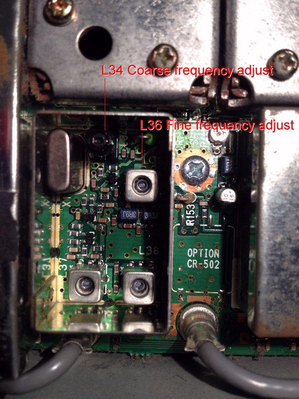
Location of frequency adjustments in the original 706
Disclaimer: The author assumes absolutely no responsibility, under any circumstances, for what the reader may do with this information. Building and connecting circuits, and performing adjustments or modifications, may damage your radio, void your warranty, and/or cause it to operate in violation of FCC rules and Type Acceptance, etc, unless you are very careful.
Continued…
I have attempted to adjust my original IC-706 (not MK2) as per the suggested procedure and turned L34 and L36 a couple turns either direction and while swapping between CW and CW-R. The two tones do not match and adjustments of L34 and L36 do absolutely nothing. Not sure where to go from here.
Hi Harold! – Just a short note to thank you for your information on calibrating the Icom 706. After a fail of my PLL board and a replacement from the States, I set about replacing the board and realigning it. This included recalibrating the main oscillator. Your advice using CW/CWR and audio software (Digipan for me) worked a treat. The tiny pot (R602) does not allow very fine adjustment but I completed the work ‘by ear’ with a gentle hand. Later I managed to get a scope on the reference frequency check point P681 and it was remarkably close. Thanks again. Saved me sending it in to the shop!
is there a way to get stereo sound out of the 706?
would be great to have sound in both sides of the headphones
I realize this question was asked 4 years ago but in any case for the future reader.
Take the head off the radio and look behind theres a white switch that selects headphones or speaker.
Excellent Information, I have to ditto what VE2AYX Claude Arcand spoke about the procedure for Frequency Calibration of the IC-706MK2g. Performed this on my mobile rig and the results were awesome. Thanks you ! 73
Super good info! Thank you! Saved me tons of time and aggravation of messing with test equipment. 73s and God bless
HI,
Your procedure to check/adjust the frequency on the IC-706 xx is Absolutely PERFECT, Simple and efficient.
Thank You
VE2AYX
oi pode me ajudar eu tenho dois radios um ic 706mk e um ic706mk2g preciso do schamatic dele pode me ajudar
Hi,
The Service Manual is on-line and free. It’s a big PDF and takes a while. Schematics are near the end of it.
Here is one: http://www.hamanuals.com/MMans/7062gsvc.pdf
73, kv5r