© 2003-2011 by Harold Melton, KV5R. All Rights Reserved. Rev.06/11/05
rough-in your tuner before transmitting!
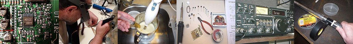
Here’s yet another case of buy for $100 or build for $20… Dave Benson, K1SWL, of Small Wonder Labs, sent me this neato noise bridge circuit. I put it in a little box and added battery, switches, and connectors. The PCB and its parts were $17 delivered. My box isn’t very pretty, but it works great! I use it to tune up the antenna tuner on 60, where it’s not legal to transmit dead carrier.
What it does:
A noise bridge makes broadband noise and feeds it through a bridge circuit to a receiver. It is first calibrated to a known, desired resistance, (say, 50 ohms) then the “unknown” load is connected. Now it starts to get interesting. By tuning the receiver and listening for the null, you can determine the resonant (or notch) frequency of various tuned circuits like traps, antennas, or even antenna tuners, without transmitting! I built mine primarily as a “tuner-tuner” to use for Field Day, so I can tune the tuner without creating QRM or desensing the other radios in the Field Day operation. It will also come in handy to prune my multiwire fan dipole. Besides all that, it’s just plain neato because it’s old-fashioned, cool, useful, and not everybody has one!
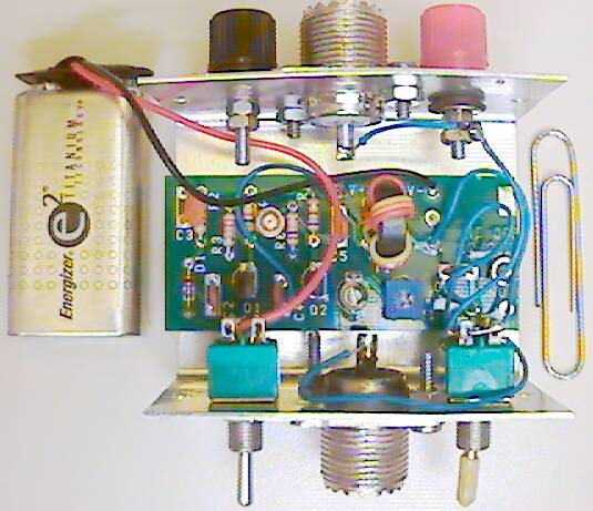
Has both banana jacks and coax connector.
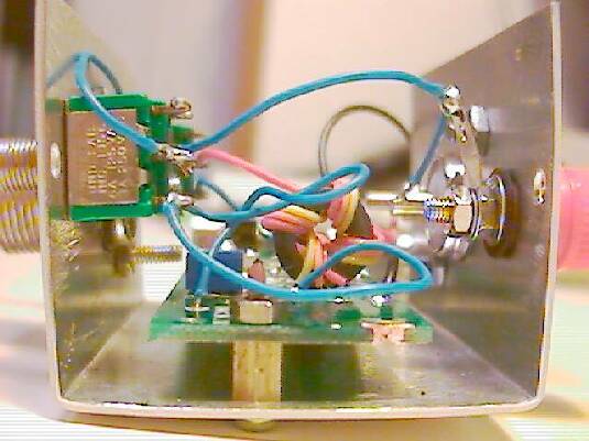
Power switch, output to receiver, and bypass switch.
CAUTION!!
If you transmit into the noise bridge, it might FRY it! Always make sure the bypass switch is on “Bypass” before transmitting!
Notes:
- If you get a three-pole double-throw switch you can eliminate one switch.
- The bypass should handle at least a couple hundred watts.
- The chassis is ground for everything.
- The battery fit inside but it’s so tight I had to wrap it with tape. I attached the battery to the lid with a cable-tie through two holes. It’s too tight a fit for a battery clip! If you do this project, use a little bit larger box!
- Get the kind of banana jacks that will accept lugs, tinned wires, and banana test leads. Handy.
- The board doesn’t have any mounting holes! I squeezed one between R4 and R6, and another one at the extreme right edge (see photo above).
(Photo above) The “bulge” is in the cheapo camera lens, not the box… I had to grind about ¼″ off the PCB to get it in this tiny box.
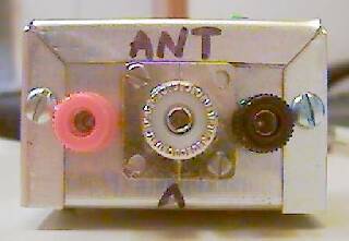
OKAY! So a coat of white paint and computer-printed labels would make it look nice.. I was in a hurry!
To use as a tuner-tuner: First, calibrate the bridge to 50 ohms resistive, with no reactance:
- Connect it to your receiver, set at 10 or 15 MHz (or about mid-range of were you plan to use it).
- Turn on/inline.
- Connect it to the antenna tuner with a patch cable (and always use same one thereafter).
- If the tuner has an internal dummy load, select it (on the “Bypass” side of the dial). If not:
- Solder two 100-ohm precision resistors together in parallel and install them in a PL-259. Place this at the Antenna jack of your tuner.
- Adjust the trimmer cap and the pot very carefully for the best possible null in the noise. When perfect, you can turn the bridge power off-on with no change in sound. The bridge is now balanced to 50 ohms resistance and no reactance. By placing the pure resistance at the antenna connector of the tuner, you have balanced the bridge for both resistance and stray capacitance of the coax patch cable and the antenna tuner (make sure the tuner is in “bypass” to the dummy load!).
- Now remove the resistor and connect the Ant side to the antenna tuner.
- Adjust the tuner for the null.
- You have now adjusted the tuner so that it looks like a 50-ohm resistance with no reactance( i.e., exactly what your radio wants to see).
- Turn OFF and BYPASS the bridge. ( !! )
- Transmit with low power and fine tune the settings on the antenna tuner if necessary.
Pros and Cons:
- After some practice, you’ll find that tuning the tuner by ear is much faster and more intuitive than watching SWR needles. You may even discover more tuner combinations with better (wider) Q, as I did on several bands.
- The Q of the bridge isn’t very high. That means it’s fairly easy to calibrate, but doesn’t give a very sharp null.
- It works much better on 20 meters and above than on 17 and below. On 80 meters, you can ballpark it but may still have to transmit to fine-tune the tuner.
- This bridge has it’s pot and trimmer on the pcb. Converting to external ones, with big pointer knobs, would allow it to be scaled to show resistance and reactance. As-is, the unit is more than sufficient to allow one to ballpark his tuner, traps, and driven elements — without the high expense of antenna analyzers! It’s well worth the $24 I have in it, and replaces units costing four times as much.
Thanks, Dave!
2013 Update
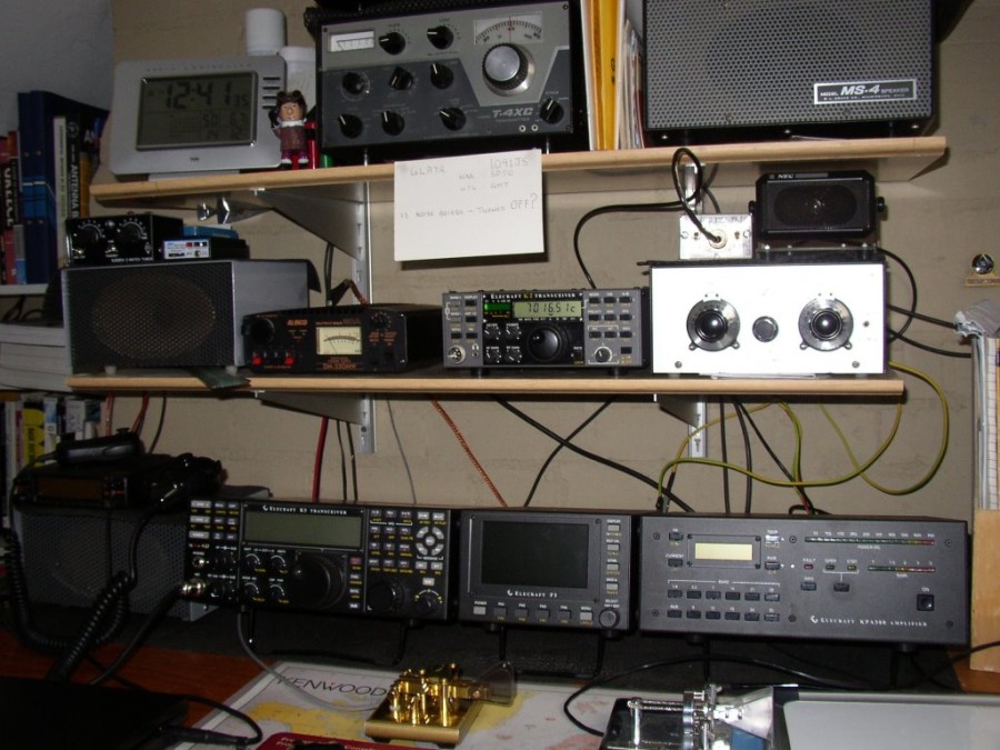
I believe this was the last noise bridge that Dave Benson made, in 2003. I recently received an inquiry from G4AYR about it, and since I wasn’t using it, I sent it off to him! So it now has new home near Oxford, England. Here’s a picture of Terry’s nice station:
Another option for QRM free tuning is the Palomar RX-100 Noise Bridge. These have not been made for years but they sell for $25 or so at tailgates.
Great for QRM free tuning, and they can do a lot more if you do not want to use your antenna analyzer. I use mine when working portable as its a lot smaller than the MFJ-259B.
73.
Lew, N9WL
thanks Lew, I just bought one to try. Cost me $30 with shipping *grin*.
hiya Harold,
all the very best for 2018.
gl good health, bridge still in constant use.
Terry G4AYR
Hey Terry GTSY!
is any one making a noise bridge kit anymore?
MFJ has one but it’s $80…
The QRP Guys produce a kit for $15. Check qrpguys.com for lots of other useful and inexpensive kits.
Here is the kit link:
http://qrpguys.com/k7qo-noise-bridge
Thanks for that info! Good to see there’s a group out there making kits again!
happy new year to you harold.
greetings from oxford
terry G4AYR
Acopy of the circuit will be greatly appreciated. A list of components, if you please, too. Best. LU2IP – Sergio.
See newenglandqrp.org/files/noise-bridge-instructions.pdf — that’s the document that came with it. It doesn’t show PCB traces but it’s simple enough to figure out from the parts layout and schematic.
Jan 2018 — here’s a working link http://www.radiomanual.info/schemi/ACC_instrument/Small_Wonder_Labs_Noise_bridge_sch.pdf
G’day Terry,
Guess who’s been checking up on you?
A nice looking set up you have; …nice looking morse key; …nothing like we had during our 15 year old Boy Entrant trainee Telegraphist morse training days at RAF Cosford!