Appendix M with Graphics
NEAR-VERTICAL INCIDENCE SKY-WAVE (NVIS) PROPAGATION CONCEPT
M-1. Evaluation of Communications Techniques
The standard communications techniques used in the past will not support the widely deployed and the fast-moving formations we intend to use to counter the modern threat. Coupling this with the problems that can be expected in deploying multichannel LOS systems with relays to keep up with present and future operation, high frequency (HF) radio and the near-vertical incidence sky-wave (NVIS) mode take on new importance. High frequency radio is quickly deployable, securable, and capable of data transmission. It will be the first, and frequently the only, means of communicating with fast-moving or widely separated units. It may also provide the first long-range system to recover from a nuclear attack. With this reliance on HF radio, communications planners, commanders, and operators must be familiar with NVIS techniques and their applications and shortcomings in order to provide more reliable communications.
M-2. Problems Encountered in Propagation of Radio Waves
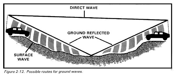
Under ideal conditions, ground wave component of a radio wave becomes unusable at about 80 kilometers (50 mi) (fig 2-12). Under actual field conditions, this range can be much less, sometimes as little as 3 kilometers (2 mi). Sky waves, generated by standard antennas (for example, doublets) which efficiently launch the sky wave, will not return to earth at a range of less than 161 kilometers (100 mi). This can leave a skip zone of at least 80 to 113 kilometers (50 to 70 mi) where HF communications will not function. This means that units such as long-range patrols, armored cavalry deployed as advance or covering forces, air defense early warning teams, and many division-corps, division-brigade, division-DISCOM and division-DIVARTY stations are in the skip zone and thus unreachable by HF radio even though HF is a primary means of communication to these units.
M-3. Concept of Near-Vertical Incidence Sky-Wave Radiation
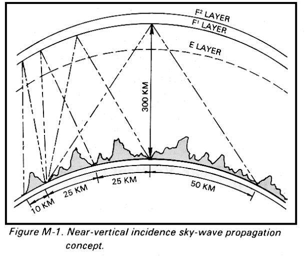
Energy radiated in a near-vertical incidence direction is not reflected down to a pinpoint on the Earth’s surface. If it is radiated on too high a frequency, the energy penetrates the ionosphere and continues on out into space. Energy radiated on a low enough frequency is reflected back to earth at all angles (including the zenith), resulting in the energy striking the earth in an omnidirectional pattern without dead spots (that is, without a skip zone). Such a mode is called a near-vertical incidence sky wave (NVIS). The concept is illustrated in figure M-1.
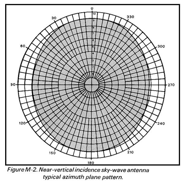
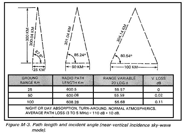
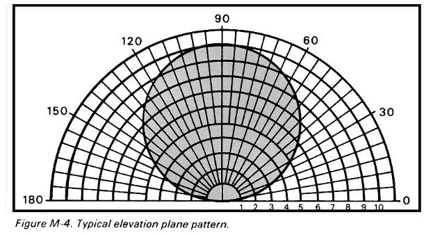
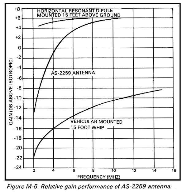
This effect is similar to taking a hose with a fog nozzle and pointing it straight up. The water falling back to earth covers a circular pattern continuously out to a given distance. A typical receive signal pattern for antenna AS-2259/GR is shown in figure M-2, and the path length and incident angle are shown in figure M-3. A typical elevation plane pattern is shown in figure M-4. The main difference between this short-range NVIS mode and the standard long-range sky-wave HF mode is the lower frequency required to avoid penetrating the ionosphere and the angle of incident signal upon the ionosphere. In order to attain a NVIS effect, the energy must be radiated strong enough at angles greater than about 75 or 80 degrees from the horizontal on a frequency that the ionosphere will reflect at that location and time. The ionospheric layers will reflect this energy in an umbrella-type pattern with no skip zone. Any ground wave present with the NVIS signal will result in undesirable wave interference effects (such as, fading) if the amplitudes are comparable. However, proper antenna selection will reduce ground-wave radiated energy to a minimum, and this will reduce the fading problems. Ranges for the NVIS mode are shown in figure M-3 for typical ionosphere height and take-off angles. Since NVIS paths are purely sky wave, the path losses are nearly constant at about 110 dB +10 dB. Relative gain performance of the AS-2259/GR NVIS antenna is shown in figure M-5. This is significant for the tactical communicator because all the energy arriving at the receiving antenna is coming from above at about the same strength over all of the communications ranges of interest. This means the effect of terrain and vegetation (when operating from defiladed positions such as valleys) are greatly reduced, and the receive signal strength will not vary greatly.
M-4. Assessment of Characteristics of Common Antennas
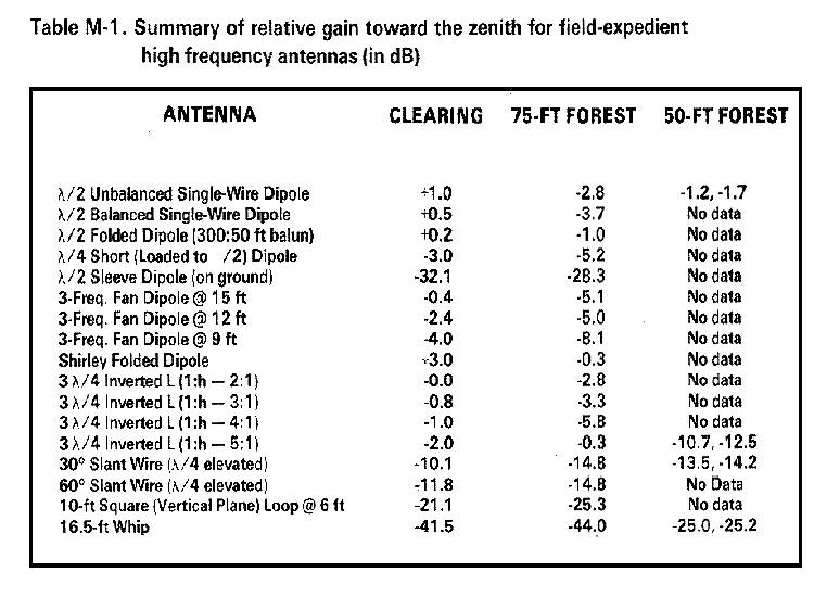
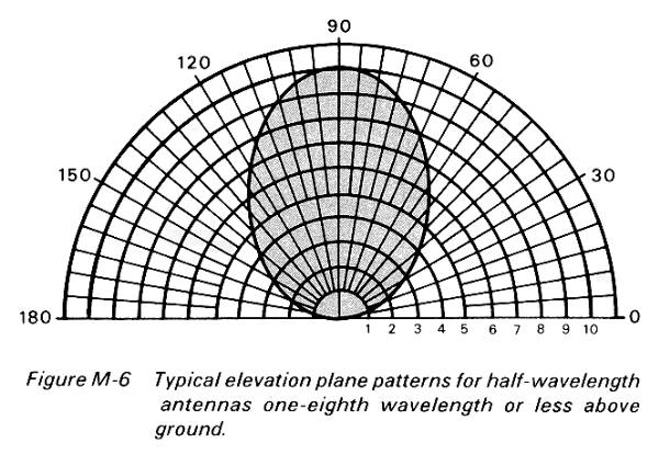
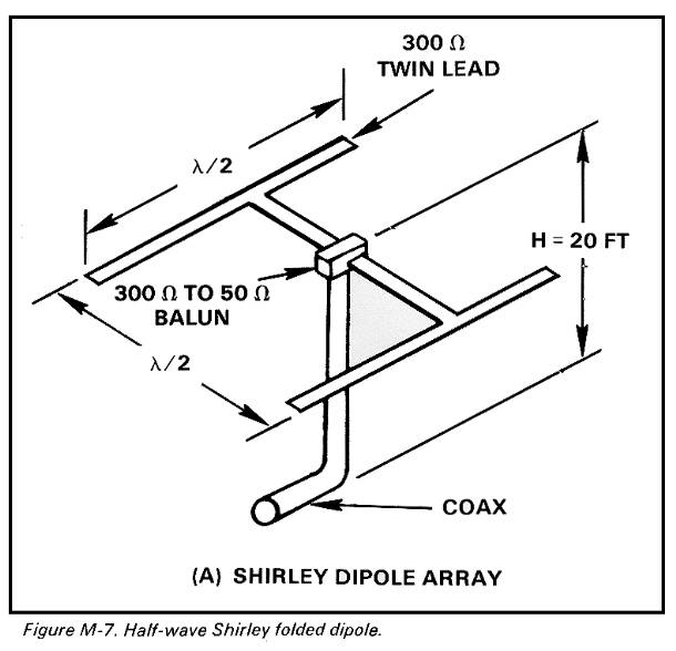
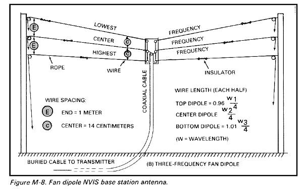
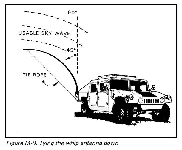
It is obvious that the Army needs short-range HF communications in the 2-30 MHz frequency band in the 1985-1990 time frame and beyond. The problem, however, is to obtain the required radiation characteristics. This is not difficult, because half-wave dipole antennas located from one-quarter to one-tenth wavelength above the ground will cause the radiated energy to be directed vertically (fig M-6). Table M-1 shows the relative gain toward the zenith of the most common types of HF antennas. This table shows that the half-wave Shirley folded dipole (fig M-7) has the most gain towards the zenith (with the other dipoles being almost as good). The Shirley dipole is a good NVIS base station antenna, but it is limited to a band of frequencies within about 10 percent of the design frequency. The fan dipole (fig M-8 and table M-1) performs almost as well, and it provides more frequency flexibility (for example, day, night, and transition period frequencies). For tactical communications, these dipoles can be easily deployed in a field expedient manner because they can be located close to the ground. For mobile or shoot-and-scoot type operations, vehicular-mounted antennas are required. This is the standard 5-meter (161/2-foot) whip bent down to a horizontal position (fig M-9). In this configuration, the whip is essentially an asymmetrical dipole (with the vehicle body forming one side) located close to the Earth. A significant amount of energy is directed upward (fig M-6 for typical pattern) to be reflected back by the ionosphere in an umbrella pattern. For use, while operating on the move, the whip antenna must be tied across or parallel to the vehicle or shelter. This configuration is like an asymmetrical open-wire line, and it also directs some energy upwards although with less efficiency. There are still no skip zones, but received signal levels are weaker than with the whip tied back as shown in figure M-9.
M-5. Orientation of Antenna
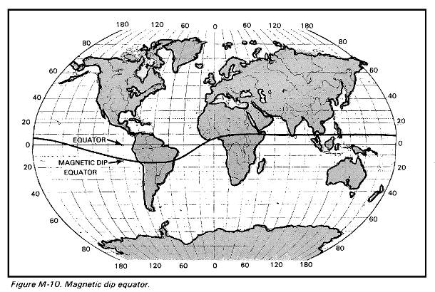
Wire dipole antennas have always been sited so that the broadside of the antenna was pointed toward the receiving station(s). This is still the correct approach for long-haul paths. This antenna orientation is not necessary when using the NVIS mode. For NVIS operation, antenna orientation does not matter since all the energy is directed upward and returns to earth in an omnidirectional pattern. This means that the dipole should be erected at any orientation that is convenient at the particular radio site without regard to the location of other stations. This holds true except when operating in the region of the magnetic dip equator (fig M-10). When operating near the dip equator (such as, within 500 kilometers (311 mi)), the dipole antennas should be oriented in a magnetically north-south direction for greater receive signal levels for all NVIS path bearings. Antenna orientation broadside to the path direction must be retained near the dip equator and elsewhere for longer sky-wave paths.
M-6. Problems in Using the NVIS Concept
While use of the NVIS technique does provide beyond line-of-sight, skip-zone-free communications, there are some drawbacks in its use that must be understood in order to minimize them.
Interference Between Ground Wave and Sky Wave.
Where both a NVIS and ground-wave signal are present, the ground wave can cause destructive interference. Proper antenna selection will suppress ground-wave radiation and minimize this effect while maximizing the amount of energy going into the NVIS mode.
High Take-Off Angles.
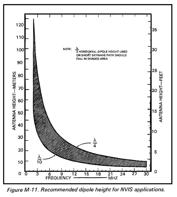
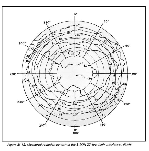
In order to produce radiation which is nearly vertical, antennas must be selected and located carefully in order to minimize the ground-wave radiation and maximize the energy radiated towards the zenith. This can be accomplished by using specially designed antennas such as AS-2259/GR or by locating standard dipole (doublet) antennas one-quarter to one-tenth wavelength from the ground in order to direct the energy toward the zenith (fig M-11). A typical measured dipole pattern (power gain) is shown in figure M-12.
Critical Frequency Selection.
As in all sky-wave propagation, there is a critical frequency (fo) above which radiated energy will not be reflected by the ionosphere but will pass through it (TM 11-666). This frequency is related approximately to the angle of incidence.
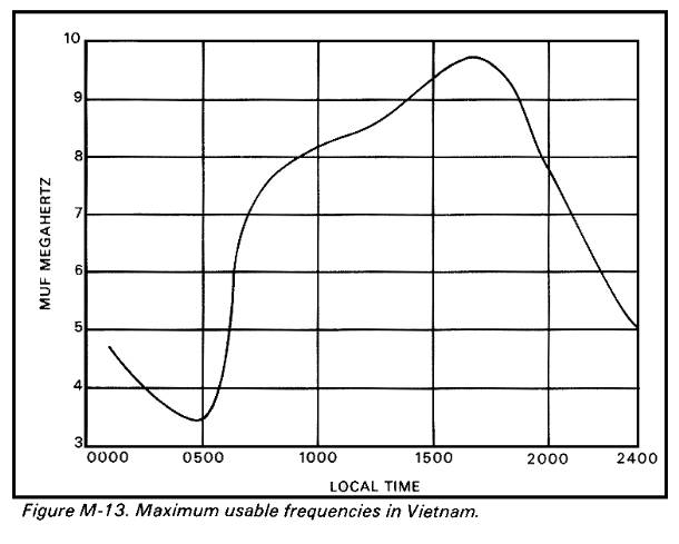
This means that the useful frequency range varies in accordance with the path length. The shorter the path, the lower the MUF and the smaller the frequency range. In practice, this limits the NVIS mode of operation to the 2-to 4-MHz range at night and to the 4- to 8-MHz range during the day (fig M-13). These nominal limits will vary with the 11-year sunspot cycle and they will be smaller during sunspot minimums (for example, 1985-86). This restriction of the frequency range is due to the physics of the situation and cannot be overcome. Some problems can be expected when operating on the NVIS mode in this portion of the HF spectrum.
The range of frequencies between the MUF and the LUF is limited, and frequency assignment may be a problem.
The lower portion of the band which supports NVIS is somewhat congested with aviation, marine, broadcast, and amateur radio which limits frequencies available.
Atmospheric noise is higher in this portion of the HF spectrum in the afternoon and night.
Man-made noise tends to be higher in this portion of the HF spectrum.
M-7. Advantages in Using the NVIS Concept
After the foregoing problems are overcome, there are many advantages in using the NVIS concept.
The tactical environment.
- There are skip-zone-free omnidirectional communications.
- Terrain does not effect loss of signal. This gives a more constant received signal level over the operational range instead of one which varies widely with distance.
- Operators are able to operate from protected, dug-in positions. Thus tactical commanders do not have to control the high ground for HF communications purposes.
- Orientation of doublets and inverted antennas become noncritical.
The EW environment
ù There is a lower probability of geolocation. NVIS energy is received from above at very steep angles, which makes direction finding (DF) from nearby (but beyond ground-wave range) locations more difficult.
ù Communications are harder to jam. Ground-wave jammers are subject to path loss. Terrain features can be used to attenuate a ground wave jammer without degrading the desired communication path. The jamming signal will be attenuated by terrain, while the sky-wave NVIS path loss will be constant. This will force the jammer to move very close to the target or put out more power. Either tactic makes jamming more difficult.
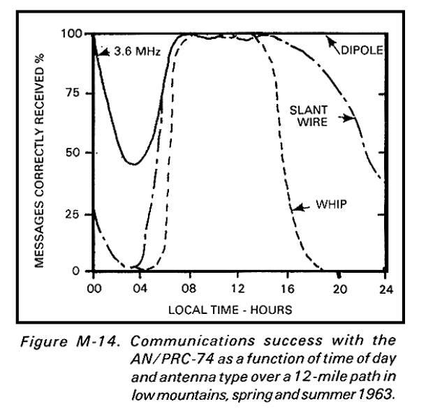
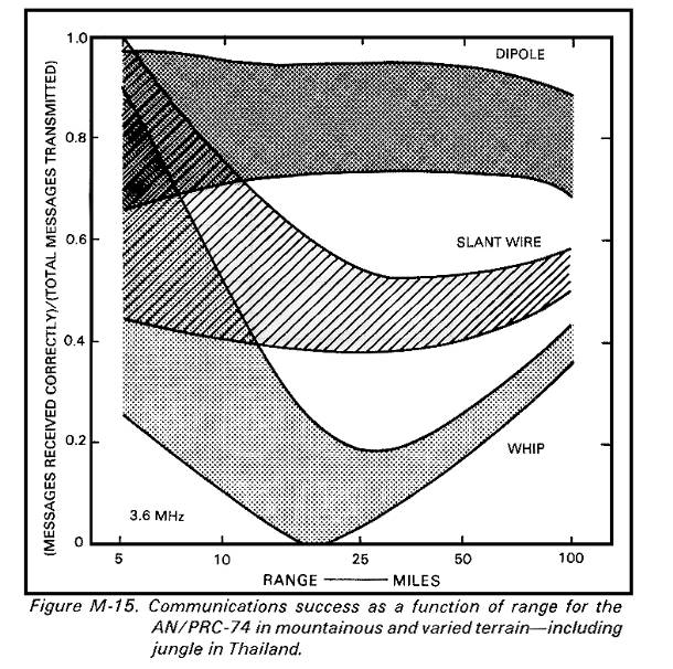
ù Operators can use low-power successfully. The NVIS mode can be used successfully with very low-power HF sets. This will result in much lower probabilities of intercept/detection (LPI/LPD). Figures M-14 and M-15 show results obtained in Thailand jungles and mountains with the 15-watt AN/PRC-74 operating on one SSB voice frequency (3.6 MHz) over a 24-hour period.
15-watt AN/PRC-74 operating on one SSB voice frequency (3.6 MHz) over a 24-hour period.
M-8. Conditions Under Which to Use the NVIS Concept
Near-vertical incidence sky-wave techniques must be considered under the following conditions:
- The area of operations is not conducive to ground-wave HF communications (for example, mountains).
- Tactical deployment places stations in anticipated skip zones when using traditional frequency selection methods and operating procedures.
- When operating in heavy wet jungle (or other areas of high signal attenuation).
- When prominent terrain features are not under friendly control.
- When operating against enemy ground-wave jammers and direction finders.
◄— NVIS Page 8 — Simple 2-meter Antenna —►

On Figure M-11, the vertical axes should interchange labels. The axis on the left side should be labeled as “feet”, while the axis on the right should be labeled as “meters”. Then the numbers will be correct.
I have a stupid question to ask.
If I build/buy a three or four band Fan Dipole 160/80/60/40 to string between two or more widely spaced Oak Trees … for Comms in the three local counties, how is it that, say, the 40m signal is able to get past the three horizontal wires of the three higher bands which are vertically strung-out just above the lower (40m) dipole?
The wires above surely must act like the reflector on one of my many Yagi’s .
Or, consider the Counterpoise laying on the ground to assist some NVIS Dipole designs.
I have 2m and 73cm yagis. They have “reflectors” at the back end.
A reflector is generally 5% longer, and .2-.25 wave away from, the driven element. In a fan dipole the other wires are much too close, and far different length, to act as a reflector. They do, however, interact enough to change the tuning, hence the need for lots of pruning to get each wire tuned to the desired frequency. They work because the resonant wire accepts most of the power, and the rest of them are at a high impedance so they don’t do much. If you do build a fan dipole, best practice is to put 6″ separation between them at the feed-point, and several feet at the ends. Even better is to run them different directions like 60-90 degrees apart (requires more trees tho).
73, –kv5r
Why is the feed line to antenna wiring arrangement for the Shirley dipole never described in the literature? There are many ways it could be configured and I just wonder what the correct arrangement is.
I donno! But a quick search yields http://arrl-ohio.org/SEC/nvis/nvis.pdf , where on page 10 it states the feed was equal lengths of parallel feeders connected in parallel at the tuner. They apparently used “mine detonator cable,” which was a twisted pair with about 150 ohms impedance. I imagine 300 ohm window line would work as well, if not better.
73, –KV5R
On company with Dick I ran a QSO with a UK station(South) on 2.5W at Saevedalen i Gothenburg with a loop-antenna length 42,20 m at 3 m above ground feeder 12,24 m 450ohm laddar Line. He used 100Watt! He got 58-59
and we got 41-52.5 years ago and his call sign was G6TUH, as I can recollect it.
He did NOT believe us! We used my FT817(not ND!) with MC 12V 17Ah gel Accumulator from a park in JO67AR.
THE LOOP ANTENNA WAS A PURE EXPERIMENTAL ONE,it was tuned for 40M BAND QRP QRG I.E 7.090MHz.
Path was 1006km in vincinnity of
Brighton sourjcoast of UK.
[quote]”kv5r on August 3, 2015 at 11:14 PM said:
You appear to be correct! The labels on M-11 are reversed in the original scan.”[/quote]
So is the M-11 diagram (shown above) correct now?
You can see from the numbers that it is not. I do not have the printed field manual to modify and rescan. The words “feet” and “meters” are on the wrong sides but since we know there are about 3ft/m we can tell which is which on the graph.
You might want to edit the caption of M-11 to note the reversed tags…???
There appears that sections of the report have been removed for security reasons but as a quick read in, it does a good job.
Used NVIS during my ops/com courses in 1983. Only took one overnighter, but the AS-2259 was a real sweet antenna. We also walked with a whip extended and held horizontal by a second person via a length of cord.
Yeah the 2259 was a great HF antenna because it was simple (self-guyed 2-band crossed dipoles), and used a no-loss air-dielectric feed (the mast) but was and is, like all things with a mil-spec #, ridiculously over-priced. Fortunately, one can build same using any wire, with fiberglass or wood pole, and 1″ windowed ladder-line — and the obligatory tuner — and achieve the same results.
I think the feet and meter antenna heights scales in figure M-11 are reversed. I.E. 10 foot antenna height will not the same effect as a 33 meter high antenna as shown. However, a 33 foot high antenna will be identical to a 10 meter high antenna!
Dave K3GAU
You appear to be correct! The labels on M-11 are reversed in the original scan.
Good catch ! N5jdk