
Copyright © 1999-2016 by Harold Melton KV5R. All Rights Reserved.
Understanding Shortwave Antennas: Page 8
Simple Antennas
Now that we know our antennas should be resonant, let’s see how to make them resonant.
First, are we transmitting or receiving? Transmitting antennas are much more critical than receiving antennas, although a receiving antenna can transmit if it is resonant (or otherwise matched) and if it can handle the transmitter’s output power. A transmitting antenna can also receive, and will do so particularly well on the frequency for which it was designed.
If you are running a CB or HAM station, you already know something about transmitting antennas. Amateur operators, in particular, must pass exam questions on antenna design and theory.
If we are operating a shortwave radio, we want it to quit fading out in the middle of our favorite shows.
Now that you are ready to get brilliant, learn rule #1 of antenna design: All antenna designs are a mixture of compromises. Just like boat hulls and airplane wings.
What we need to do, therefore, is identify our particular need and design an antenna which is optimized to fulfill that particular characteristic - whether it be directionality, gain, or bandwidth, or just all-around good performance.
I have been an antenna experimenter for over 35 years. My goal has always been to build cheap, simple antennas that work well. It’s all in the numbers. I once had a $25 multiband shortwave antenna in the attic that performed as well as any $150 manufactured SW antenna. I had a discone scanner antenna made of brazing rods and a PL-259 that I built for about $10. I once built a 10-element 2-meter yagi from scrap TV antenna parts. Some of my other antennas are shown in articles on this site.
You can string up a wire just about anywhere and get a good signal on shortwave. Fifty feet of very fine wire, strung along the ceiling on thumbtacks, will give you much more signal than the telescopic whip that comes with portable radios. Telescopic antennas are way too short for shortwave frequencies!
There is one fundamental rule for receiving antennas: It must be at least ¼-wave long at the lowest frequency you plan to use. Thus, if your lowest regular listening is on 3315 kHz, your wire should be 70 feet long - minimum. Obviously, the 5-foot whip antenna on your shortwave is just a bit too short. For much better performance, it shoud be ½ wave long on your lowerst frequency (a Zepp). Multiwire fan dipoles are best of all.
Let’s design a decent longwire antenna for general shortwave listening. We will want to listen down to 2500 kHz (2.5 MHz), then analyze its performance.
The formula for determining the ½ wave length of wire is: 468 ÷ f (MHz) = feet.
In our example, 2.5 MHz is our lowest frequency, therefore: 468 ÷ 2.5 = 187.2 feet of wire. That’s a lot more than most city lots can handle!
Okay, let’s say we’ll design it for 5 MHz, and be willing to accept slightly reduced performance down to 2.5: 468 ÷ 5 = 93.6 feet of wire. We can handle that.
Longwires are usually strung up something like this:
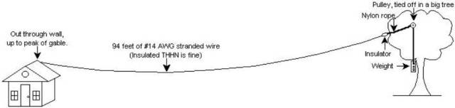
This arrangement keeps constant tension on the wire while allowing the tree to sway without breaking the wire.
Electrical suppliers carry 500-foot rolls of #14 stranded THHN wire (about $50). Electricians frequently have scraps and partial rolls. Farm supply stores carry #17 aluminum fence wire (about $15 for ¼-mile roll). Any wire will do — but some will last longer than others. Stranded, insulated wire (#14 THHN) works well.
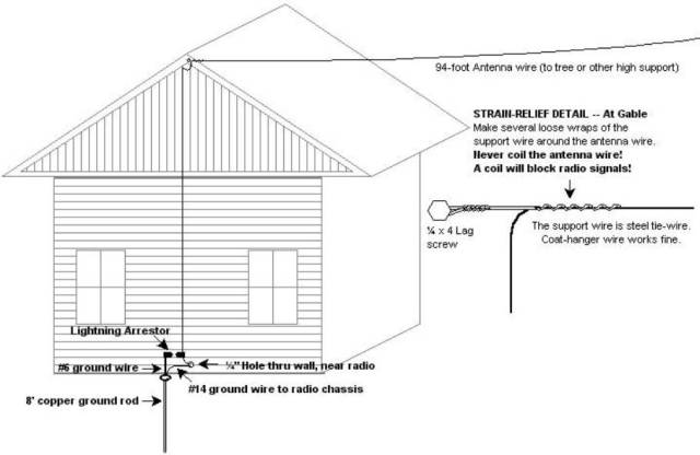
Classic Longwire Installation
This page details the installation of a relatively safe, good-performing, long-lasting shortwave antenna. The #1 rule is: Where you scrimp on quality is where it will eventually break!
Yes, you can simply hang a wire out the window. But experience shows that a properly installed antenna that is mechanically and electrically sound, and a properly grounded radio, will consistently yield better performance and reliability. It really is worth the extra effort to use good materials, solder, and weather-proofing.
Wires should be insulated, stranded #18 - #14. A jack may be soldered on to plug into your radio. If the radio has no external antenna jack, solder an alligator clip to the antenna wire and clip it to the telescopic whip.
Which Direction Is Best?
Usually, directly away from overhead power lines.
If the lines run across the back of your property, go up the back of the house, over the roof, to a tree in the front yard. If the lines run across the front of your property, go up the front (or side) of the house, over the roof, to a tree in the back yard. You can also run a wire along eaves and/or the top rail of a wooden privacy fence.
Run the longwire as far from, and as perpendicular to, the power lines as possible. This will help reduce noise. If you have buried power lines, run your antenna any way you like. In the USA, pointing your longwire northeast will help bring in European stations in the daytime, on the higher shortwave bands.
Continued…
Hi Harold I used to listen to shortwave and have recently inherited a JRC SRD 535D HF Receiver from my father in law. This radio has digital tuning and I can’t wait to install a long antenna to listen to the signals.
I am looking for a manual for this radio. Thank you for providing this webpage and I will be following your advise an installing an antenna.
Thank you!
Barry
This is an excellent resource, thank you! I strung up 100 feet of 24 ga speaker wire in a few trees. It enters the house through a window and is soldered to coax which plugs into radio antenna jack.
I plan on adding a 200 foot + wire for am radio dxing. I’m in Minnesota, Nashville and Winnipeg are the furthest I have recieved.
Do I need to run a ground from the coax outside to ground?
I experimented and the rain gutter picks up 41 meter band beautifully. But its lousy for am radio.
Howdy Rob,
Depends on what antenna. If it’s an end-fed long-wire, yes, you should ground the coax shield outside. Otherwise, it’s not transmission line, just an extension of your long-wire.
For good AM band long-wire, a quarter-wave at .55 is 234/.55=425 feet of wire. More than most people can run.
Look at a Loop-on-Ground antenna; 30-60 feet square should work nicely. See the comment (and links therein) on page 10 of this article.
73, –kv5r
Thank you!
I have ordered a GODAR USA DXR1000 SW vertical antenna. This vertical antenna is mounted on a steel bracket which I’m assuming is insulated from the steel bracket as it passes through an attached steel flange with the coaxial antenna connection being on the bottom of the assembly. In turn, the antenna and its bracket will be mounted to the top of an existing steel tube tower which is grounded at the bottom of the tower with solid copper 8 gauge wire to a 3 ft long steel grounding post fully embedded in the ground. In a lightning strike, my logic (perhaps twisted) leads me to believe that if lightning first hits the vertical antenna, the lightning will then jump to the metal tower and disipate at the bottom of the tower since the tower itself is grounded.
Is my logic flawed? I will appreciate your thoughts and reply. Also, if it should be of any consequence; when there is the slightest threat of storms, I always disconnect my antenna feed line from my SW receiver, but keep the receiver’s antenna ground connected to a cold water pipe. Waiting for your reply.
Yes, that sounds good to me. Lightning should initially follow the path of least resistance then build up a plasma arc and discharge. Keep in mind it may also follow guy wires and coax, even if such things are not considered grounded.
Disconnecting from the radio is always essential, as even nearby strikes (much more common than direct ones) will induce a voltage spike in the antenna and blow the radio. It’s not uncommon to see and hear a fat spark jump across your coax connector during storms, just from magnetic induction (the EMP pulse), not a direct strike.
73, –kv5r
Thank you so much. I’m new to your website and its useful information. I will have a question(s) later regarding one of your many antenna plans for a long wire; but first I will try my new GODAR USA DXR1000 SW vertical antenna. Thanks again!
Sir, (would address you by your name if I knew It)
While I’m waiting for my GODAR USA DXR1000 SW vertical antenna to arrive, I have a few questions:
I have read that vertical antennas may be more susceptible to noise than long wire antennas. I have an electrical power line to my home which will be about 34 feet from my vertical antennas once it is mounted on my tower.
What would be the effect if I were to mount the vertical antenna horizontally and pointing away from and perpendicular to the electrical power line running horizontally? Could it Improve reception or make it worse? Also, in this position, with the coax feed line still descending vertically, would that configuration fall into the so-called Zepp category?
These are questions that recently popped up in my mind.
Please respond and I appreciate your help.
You do realize, I hope, that the GODAR antenna you are getting is a 59 inch telescopic whip, with a half-wavelength frequency of 95 MHz…? As such, it’s not going to do much below the FM broadcast band. Way down in shortwave bands, it will be only very slightly better than the whip on a portable shortwave radio, only because you can put it outside. And telescopic whips don’t last long outside, because they corrode between the sections.
No, pointing the little whip directly away from your power line won’t do much if any good. If the line is radiating noise, it will be coming in from lots of power line that is way off axis to the direction you are pointing it.
You need a minimum of ~35-65 FEET of antenna to do any good on shortwave, and 100-135 feet is much better on the lower SW bands (at night).
But wait! A lot of low-band DXers are discovering the “LoG” (Loop on Ground) receiving antenna. The LoG antenna puts out a very low signal level, but the noise is even lower. The idea is simple: a 15 foot square loop (60′ of insulated wire) right on the ground, in the grass, held down with wire garden staples, is connected to coax with a small isolation transformer. The receive pattern is like a dome, from horizon to horizon.
See it here – http://www.kk5jy.net/LoG/ .
I’m gonna be building one soon, and will write an article about it.
73, –kv5r
Thanks again for your response. It seems I made an error in purchasing this antenna. If it turns out be a dog, I will definitely construct one of the long wire plans you have and be done with it. I will also check out the LoG plan at the URL you provided and look forward to your article after you construct your own LoG.
Mr Melton,
First, Wire & Cable Your Way.com has #14 THNN insulated wire which has 19 strands of copper wire that can be purchased in a 500 ft spool.. Please confirm this is the wire you recommend for longwire SW antennas.
Second, I have measured a space that will accommodate your 94 ft Classic Long Wire Installation design as described on page 8 and will construct the Classic design first. Later, if I can find enough space for the Outdoor Multi-Wire Antenna with Harmonics design on page 10, I will construct it as well, and with slight shortening can use the 94 ft Classic wire as the third wire on the Multi-Wire design.
I would like your comments on how I plan to construct the 94 ft Classic design: It will come off the top of a supported 30 ft tower close to the house (well away from house power line), first with a short length of nylon rope tied to an insulator with the 94 ft wire attached to a second insulator at the far end which in turn will be tied to another longer nylon rope slung over the slight V of a tree limb, also 30 ft high, and attached at the end with appropriate weight to keep the wire taught (not too taught), but allowing the tree to move with the wind, which in itself should allow strain relief on the wire.
Before I address some confusion (on my part) regarding the support wire, let me say I’m uncertain if I can tie off a pulley in the tree without killing myself in the process. But I believe the nylon rope will glide over the tree limb which is fairly smooth. (Pine tree). My greatest challenge will be getting the nylon rope tied to the end insulator over the tree limb and determine the appropriate weight which will keep the wire taught, but not drag the wire end and/or insulator over the tree limb.
As described above, I will not be using a lag bolt attached to the house gable with a support wire/coat hanger. So, for the feedline/lead-in wire as shown on page 8, should I use copper-clad steel antenna wire for this wire (if so, what gauge, solid or stranded?), or can I use the same #14 THNN as the long wire antenna? Using either which you tell me to use, I’m assuming the several loose wraps of feed/line-in wire around the antenna wire should be soldered to the antenna wire; is that correct?
Also, a Balun or Unun do not appear in the drawings, so again, I’m assuming neither is needed and the feed/line-in wire can attach directly to the SW radio’s antenna attachment; is that correct? If one or the other is needed; would it be 9:1, 1:9 or are they the same; or would a different ratio be needed?
Sorry, I have to show you my ignorance; but when I was a young man with a SW radio, I just stuck the end of a wire into the radio and that was that. I’m now in my second childhood and want to enjoy once again what I enjoyed many years ago.
Finally, please respond with your wisdom and comments on all of the above; so that I get it correct. THANK YOU!
Howdy Jon, (I’m Harold, by the way; sorry, forgot to answer earlier).
Yes, #14 THHN (or THWN) stranded makes good antenna wire. Home Depot has the 500′ green for $45. Note that the thin nylon coating on THHN will u/v rot and start falling off in a few years but it doesn’t hurt anything, just looks ratty. There used to be a wire called THW that didn’t have the nylon coating over the PVC, but I can’t find it now. The “N” means nylon-coated, which is only on there to make it easy to pull in conduit.
Of course, if you wanna spend more money (per foot), copper-clad steel makes a stronger antenna. Most of it is un-insulated and will eventually corrode. But here’s one at The Wireman that’s #13 stranded insulated, $52 for 150 feet. That would make a “premium” quality antenna, in terms or durability.
I wrote this article in 1998 or so, and have learned a lot since then. I don’t like the multi-wire antenna any more, because it just isn’t necessary for SWL.
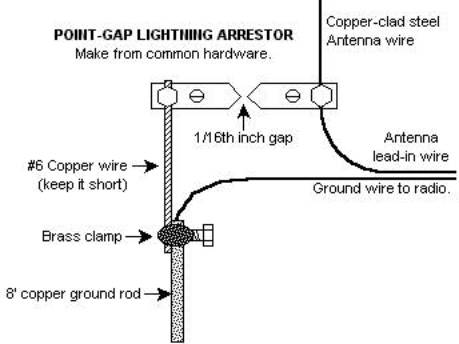
For the “classic” long-wire on this page, just run one continuous wire from the radio, to lightning arrestor (if used), up through insulator on tower, and on out to the far end. No splices to corrode, but weatherproof the connection at the arrestor (silicone caulk), and at the far end, to keep water out of the wire.
Going up 30, and out 95 or so, will actually give you the classic 160 meter inverted L antenna. It’ll work even better if you add a ground wire and/or 40 feet or so of counterpoise wire, to the radio.
No, you don’t really need any kind of balun for a SWL antenna. You’ll get plenty of signal without any sort of impedance matching. And baluns are for feed-lines, not long-wires with no feed-line.
For support lines, #36 nylon “trot-line” string will last a few years, but sunlight u/v breaks down nylon; a more permanent line (that I now use) is 3/16″ black u/v-protected dacron (~$45/500′ on amazon – click see it). No stretch, no rot, 750 lb break. The 1/8″ is ~$35 but breaks at 350.
No, a line will not slip over a swaying tree branch. Lines over branches sink into the bark and get captured after a while, if it doesn’t wear in-two first. You DO need a pulley if you’re gonna use a counterweight. Get the 50mm (~2″) stainless pulley on amazon for ~$10.
What you do is shoot a line over your branch that will pull up the line tied to the pulley. Put your antenna support line through the pulley (don’t cut the tail loose from the spool yet or the antenna line will fall out of the pulley) then just pull up the pulley, tie the pulley line off (lag screw in the trunk at 5′), then pull up the antenna, and tie that line off to the brick. Leave enough extra line (30-40′) coiled up on both lines so you can let the antenna and/or pulley down if needed.
The couple feet of spiraled stiff wire I mentioned in the article is not connected to the antenna wire. It’s just a strain-relief gripper thing. Not really needed, but if you do use one, just attach it to your insulator on the tower then run the antenna wire through the spirals. You can see where I used 4 of them in the article linked below.
See also my 80 Meter Doublet article for lotsa pictures & ideas on putting up a big antenna with a counterweight. Note I used half a cinder block on a 130′ #10, you won’t need that much weight, a house brick or two should do it.
73, –KV5R
Thanks Harold! All of the materials you mentioned above have been ordered. I’m getting pretty excited about constructing the entire Classic Long Wire.
Just a few remaining questions:
I currently have my radio’s antenna ground connected to a cold water pipe on the second floor where my “shack” is located with green #12 solid copper wire to a clamp on the pipe. A Techie with Grundig-Eton told me the radio’s ground is connected internally to both the SW coax connector and the SW wire connector (black), which is just to the right of the SW wire connector (red) and the connection I will be using. Thus,,from your comments above, I believe the grounding of the radio antenna through the radio will suffice, making the counterpoise unnecessary; is that correct?
Following your advice above to run the #13 copper-clad steel antenna wire from the radio connector up to and through the ceramic insulator’s second hole (first hole connected by 3/8” Dacron rope to tower eye bolt to separate antenna from the tower); my question is this: Instead of using the strain-relief gripper thing, can I simply loop the antenna wire a few times around the second insulator hole to provide some relief for the lead-in from the tension that will be created by the weight at the far end, or will that cause antenna reception problems?
Last question: when you mention above “. . . then just pull up the pulley, tie the pulley line off (lag screw in the trunk at 5’)“, . . . . Does that mean the lag screw should be attached to the trunk 5’ above the point where I want the pulley suspended by 5’ of Dacron rope at the height I want the far end of the antenna to be; is that correct? If not, please explain a bit further for me.
Again Harold, thanks for hanging in with me on my quest to have a perfect Classic Long Wire.
Yes, your ground should be fine.
No, I wouldn’t coil the antenna wire at the insulator. A coil will block RF at some frequency. Use a little cable clamp or something, like I show on the doublet.
No, the pulley line goes over a branch then down to the ground. Pull the pulley up with the antenna support line thru it. Tie the pulley line off to lag screw near ground level. Then pull the antenna line up and tie that to weight. No climbing required.
Thank you so much Harold,
I will let you know later how the antenna is working.
Harold, I have now received all of the items you recommended and need to build the Classic Long Wire antenna. I have two more questions:
In an earlier response you said: “Going up 30, and out 95 or so, will actually give you the classic 160 meter inverted L antenna.” Also, “just run one continuous wire from the radio, to lightning arrestor (if used), up through insulator on tower, and on out to the far end.”
By running one continuous wire of about 124’ (94’ antenna + 30’ lead-in) which will create the classic 160M inverted L; what effect, if any, might that have on the radiation patterns related to the classic long wire (Directivity) as shown on Page 9, particularly at 10 MHz? That Page also notes that, “Long Wire antennas radiate toward the far end of the wire.”
Due to the physics of my location, power line, existing trees, etc., the far end of my antenna will be westerly, away from Central Europe. I do, however, have several trees on different bearings from my tower to choose from, thus changing the direction of the four lobes (looks like a clover leaf at 10 MHz) radiating off of the antenna. I’m choosing the radiation pattern at 10 MHz because it appears to be in the middle of the most effective SW bands; and by changing the direction of the far end to bearing 215 degrees (south westerly), I can point one of the four lobes directly at Central Europe at bearing 012 degrees. I believe by optimizing the antenna at 10 MHz, the lower and higher SW frequencies will work fairly well too. Am I on the right track?
I’m having a hard time envisioning how the pulley line and antenna support line will work. First, should I shoot a Dacron rope (3/16”) line or other type of line over the branch (at the height I choose) that will pull up the line tied to the pulley which later will be pulled down to the ground and tied off to a lag screw at about 5’ above the ground. But first I put the Dacron antenna support line through the pulley while both lines are on the ground. Seems like the antenna support line should be tied to the pulley; otherwise, it will fall out of the pulley even without cutting the tail loose from the spool; as both are raised. Regardless of the type of line I use for the pulley line; should the antenna support line (Dacron) threaded through the pulley be long enough so that I can reach it from the ground so I can tie it to the weight? If the antenna line threaded through the pulley were long enough, it likely would not fall out as it is being raised along with the pulley line. I understand I need to provide even longer lengths of 40’ for each line to adequately lower each line to the ground if needed later.
You know, after going through the process of thinking it through as I have above, I think I now understand how to do it. If I allow at least 60’ for each line (height of antenna will be 30’); perhaps longer for the pulley line because the overshoot may leave the end of the rope beyond my reach from the ground; and leave 60’ of antenna support line looping back from the pulley after threading it through so I can reach it from the ground, I should be OK. But at what height would you expect the pulley to be tied off at: slightly below limb level?
Thanks again for your expected response,
Yes, the pattern will look like a daisy at higher frequencies but it won’t matter on SWL. You’ll get plenty of signal.
Shoot fishing line (or #18 nylon string) over the branch. Then use that that to pull dacron up, over, and down to the ground. Cut it and tie on the pulley. Now run dacron from the spool through the pulley, and tie it to antenna end insulator. Don’t cut it yet.
Now pull up the pulley, paying out line as needed from the spool so the insulator stays at ground level. Tie off pulley line to tree trunk. Now, once the pulley is up, cut the line from the spool (don’t let go of it!) then pull up the antenna and tie that line to your counterweight.
Once the pulley and antenna are up, don’t cut off the slack from either line, just coil ’em up, so you can let either one down later. Yes, both dacron lines will be 60 feet long.
It’s real simple; don’t overthink it.
–kv5r
Harold, I have been remiss in not writing back to you sooner to let you know I built and erected the classic long wire to one of three trees I selected that provide me with different bearings to choose from should I want to change the direction of the antenna. Each tree has two lines (antenna support and weight with pulley), one lag screw to tie off both lines, and one large hook to hold the folded excess of both lines off the ground. I only needed one brick with five holes to provide the needed amount of weight. Thanks for all the help and advice you provided!
I am, however, experiencing a lot of static and fading on many frequencies throughout the SW bands, which leads me to ask a few more questions:
I used the suggested stronger copper-clad steel wire as suggested, but in your experience what is the best metal to use from a reception/radiating standpoint? Would solid copper be best for reception, and if so; would solid copper gauge be best to use or solid stranded copper be better? I’m assuming copper would be the best metal to use, but I’m uncertain.
Would my classic long wire benefit from having a stand-alone antenna tuner or is the radio’s (Grundig-Eton Satellit 750) internal antenna attenuator (ATT) adequate? Regardless of what level I set the ATT, it does not reduce the static or fading I experience on many frequencies.
Similarly, would my long wire also benefit from having a stand-alone audio filter to reduce static and fading? And would the combination of both an antenna tuner and audio filter be even better than just either alone?
You previously said you had changed your mind about the multi-wire antenna with harmonics and you now thought the single long wire was good enough for SWL. However, when Spring/Summer return, I plan on building one just to see if a multi-wire, pre-cut to the specified frequencies would improve reception.
Please respond to my questions above, and thanks again Harold.
Jon
Hi Jon,
Static and fading are just part of shortwave. Can’t do much about either.
Wire: RF runs on the surface of wires, so there’s no difference in copper-clad steel or pure copper. Also, there’s no difference in solid or stranded, except solid breaks more frequently from bending.
Antenna tuner: a tuner will, when tuned, bring all signals (and noise) up somewhat, but if you’re already getting plenty of signal, a tuner won’t help you, except perhaps on very weak signals when noise is low enough to hear them.
Attenuator (ATT): Use it to keep from overloading the radio’s input on very strong signals. It will not improve signal-to-noise ratio, but reduce both equally.
Audio filter: like radios, tuners, and antennas, an audio filter doesn’t know the difference between signal and noise. But it can make listening more pleasant. There are DSP filters with “noise reduction” but in my experience they reduce the noise but also garble the audio and are not worth the (ridiculous) price.
Multiwire: The only reason to do that is to provide several matches to coax on a center-fed dipole. It will not be an improvement over what you have now. I suggest you next try the Loop On Ground we discussed before. Several people have reported it actually does have a better signal-to-noise ratio.
73, –kv5r
Thanks again Harold,
I will try the Loop on Ground; if not soon, then when the weather warms again. I don’t know where you are, but if your build one sooner, let us all know the results you experienced.
Jon
Hi,
First of all, thanks for all the long work and dedication to helping others enjoy the radio hobby.
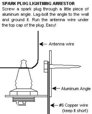
Second, I made this exact longwire antenna a few years ago working from your diagrams, with the spark plug arrestor. The spark plug is just a foot or so off the ground, mounted to the side of the house. The ground rod is right underneath. For a feed wire, I connected some RG-59 coax with “Siamese” combo wire, the type used for analog security cameras that has a pair of power wires. Despite having both the shielding around the coax AND the pair of power wires running the length of the wire, I never attached either to ground. I soldered a 1/8″ jack to the end and plugged it into the antenna input of my Realistic DX-390. It seems to work pretty well.
I just purchased an RTL-SDR unit and want to connect this feed line to it but I’d like the ground coming in to where the RTL and radio are. My plan then is to use either the shielding and/or the pair of power wires as the ground. Any preference there?
I also read on RadioReference.com (https://forums.radioreference.com/threads/sma-connector-for-sw-longwire.364513/) That I should impedance match the line and they recommended “Balun One Nine v1 – 1:9 HF Antenna Balun and Unun with Antenna Input Protection” Upon re-reading this I see it also performs input protection.
And, I read above that you possibly recommended an isolation transformer to shunt the feedline to ground. I’m unsure about all of that and my first search for that came up with expensive power isolation transformers. Probably not what you were referring to. My second search came up with: “MFJ Enterprises Original MFJ-915 RF Isolator 1.8-30 MHz, 1500W PEP, SO-239” I found on Amazon? about $40?
Thanks for the help!
I salute you: o7
(I learned that emoji playing EveOnline. pretty clever)
Howdy,
You will want to get the Balun One Nine V2, it uses a better Coilcraft transformer. Screw that onto the rtl-sdr. From the balun’s screw terminals, run twin-lead (the 300 ohm TV ribbon cable will do fine for SWL) outside. Connect one side of the ribbon to the ground wire at the spark plug, the other side to your long-wire antenna at the spark plug tip.
I would not use the CCTV cable as a transmission line, as you don’t know its characteristics in TL mode. Just use all its conductors tied together as one wire for your long wire antenna. Or better, get a roll of #14 or #16 THHN stranded insulated wire and use that for the antenna, as it’s thinner and lighter than the CCTV cable.
The “input protection” used with some rtl-sdrs is just a pair of diodes that conduct and short the input at greater than ~0.7 volts. That will clamp a voltage spike but won’t handle any current, so they handle little spikes but not anything serious like a nearby lightning strike. Always disconnect when hearing thunder! The V2 balun has a 2-part terminal block you can separate.
The isolation transformer I was thinking of would be a simple 1:1 RF transformer wound on the appropriate type toroid, like a FT-140-31 or 43. Nothing like a power transformer, except the same schematic. The idea is it would not stop spikes but would drain off DC static build-up. I don’t know how well it would pass RF.
73, –KV5R
Hi again!
Thank you very much for the reply!
I may not have described my antenna correctly. I do have a #14 THHN stranded wire for the antenna. It’s a little over 100′ I believe. Where it meets the house, it goes down the side 20′ close to the ground, to my spark plug arrestor. At that junction, the RG59 takes over and center conductor connects to the longwire.
I had never connected the coax’s shielding braid to ground. It is siamese cable and has a pair of power wires running the length of the coax.
I’m planning on using all three, braided shield and both power wires to be the ground. I was hoping that was ok.
Ah, OK, yes, that will work. Without the shield connected (at both ends), it’s just more antenna wire, not transmission line. You don’t need to use the power wires for for ground though. Just ground the shield near the spark-plug, and on the radio end put some kind of RG-59 connector (usually an F, or a PL-259 with a UG-176 adapter in it) then get an RG-316 pigtail adapter to take that to SMA for your SDR dongle.
Hope you got the RTL-SDR.com V.3, as it’s the only one with software-switchable direct sampling mode, so you can receive below 25 MHz without any HF converter.
As upgrades, you might consider (1) the Balun One Nine (and as before, change the coax to 300-ohm ribbon cable); (2) broadcast AM & FM filters (broadcast stations make intermod messes all over an RTL-SDR); and (3) a USB Type-A extension cable, so you can put the train of dongle & filters out of the way (and not bust your computer port).
Please let us know how it all works out!
73, –kv5r
I have seen a balun is recommended for these antennas to cut down on noise. Any thoughts?
A balun (actually, a common-mode choke) may reduce noise if used on a feed line (parallel or coax), to reduce the amount of in-house electronic noise getting on the feed line.
For a single wire that comes all the way to the radio, as shown above, it will make no difference, since there is no feed line to balance.
I want to build a SW antenna for RTL – SDR. I have an old antenna tower outside the house that is 30′ tall. The pole barn is ~150′ away. I can run a #14 THHN stranded from the top of the tower to the pole barn 14′ off the ground. There is some RG-6 running up the tower that I can route through the house attic and down to my computer.
There are high voltage transmission lines 1/4 mile East of my house. 765KV! Wow
Do you think I will I be able to get any signal at all if I build this antenna?
Yes, if the transmission line isn’t noisy.
Check the voltage to ground for induction from the HV transmission line; those rtl’s have little or no front-end protection. You might need an isolation transformer or something to shunt the feedline to ground.
Experiment!
–KV5R
You will have better luck if the lines are perpendicular to your antenna instead of parallel to it…
Wow, this was along time ago. I finally got around to making the antenna. It is #14 wire 161′ long running East and West. The power lines in the back field run North and South. I made Delrin insulators and brackets at each end.
I measured the voltage to ground and I have 0.536 VAC in the line.
Is this detrimental? What can I do to remove it?
It seems I am making every mistake in the book. I used solid wire instead of stranded.
I made Delrin insulators and looped the wire around the insulator and then twisted it back on itself and soldered it before dropping it down to the feed line center conductor. Is this not going to work?
https://live.staticflickr.com/65535/49740357383_d1b70eb83d_n.jpg
Yes, the wire you used should work fine, though solid will break where it flexes, sooner than stranded would.
If you measured that voltage with the antenna unterminated, using something like a DVM with the typical 10 mega-ohm input impedance, that voltage will much lower when you put a load on it, such as the receiver, or to test, across a resistor from the antenna to ground.
I did measure that voltage with a DVM unterminated. Thank you very much. that makes me feel much better.
I have a back property line that’s 255 feet long, I could attach a wire from 8 foot posts for that length. Is this too,long? Should it be an exact length? If it’s 8feet off the ground is that sufficEnt for reception? The plan is to receive only, no transmit plans. To connect the ant and to my future Radio location, does the wire that links to the radio have to be connected exactly in the middle of the antenna? The antenna will be nearly due north/south.
Yes that should work quite well for shortwave reception. Better for domestic, not so good for foreign DX, at that height. 255′ will take you down to about 1.9 MHz at good efficiency.
Connect feed-line to center if your radio has a 50-Ohm jack; otherwise, it’d probably be better to just bring one end of the wire all the way to the radio. Look at your radio’s manual to see if it wants coax or long-wire for external antenna.
I have just purchased my first portable shortwave radio, it is a tecson PL-880. I am wanting to install a point gap lightning arrester on a random length long wire antenna, I am concerned about the grounding there does not seem to be anywhere to ground the radio how would you suggest that this be done? Thanks for your help.
I looked at the manual and it doesn’t say anything about grounding it. However, if the ext. ant. jack is a 2 conductor type, the “shell” side could be grounded (with the jack’s “tip” connected to your long-wire antenna).
In any case, always disconnect the external antenna when you first hear thunder, as a point-gap arrestor will not arc until several thousand volts.
73, –kv5r
Hi Harold,
I’ve spent many hours reading your posts and I appreciate the knowledge and effort you’ve spent blogging.
I’m a bit confused about the “twisted coat hanger” you suggest for the antenna support on p8 of SW antennas. It seems that the antenna wire would slide right through the twists. So what is it accomplishing? Where is the strain relief?
This just tells you what I’ve accomplished so far:
I’ve got WSPR running and receiving stations across the country. But only after I set up an outdoor wire antenna that is 2 stories high and about 60 ft long to a tree. Used a fishing pole to cast a small weight and pulled an intermediate twine before pulling rope up through the tree. But strain relief at the near(house) end is temporary that needs to be addressed. So far I haven’t wired up any grounds or used a counterpoise. Before this antenna I tried 2 different indoor antennas that were not very successful.
I’m using a 9:1 unun at the end of the wire right before it attaches to sdr (SDRplay RP2) after coming into the house. I’m contemplating moving the unun up to the near end support and then running coax down (~25 ft) into the house.
Thanks,
Pete.
The twisted wire strain relief is just stiff wire. You wind it around a drill bit or something about the size of your antenna wire, clamped in a vise, 10 turns or so. Then remove the bit, clamp one end of the coil in vise, grab other end with vise-grips, and stretch it way out, until it’s like a very elongated corkscrew. Then put a loop in one end for lag-bolting to house. You then wind the antenna wire into that long corkscrew and it will grip the wire over its entire length (a foot or two), thus providing strain-relief.
If it slips, stretch out the corkscrew longer, or start over and make another one with a smaller I.D. The I.D., after stretching, needs to be much smaller than the wire for it to grip. As the wire pulls on, it further stretches it, gripping the wire tighter, sorta like a Chinese-finger toy.
They work really well for coax (and extension cords) but I’m not so sure about small single-conductor wire. You might need to make the corkscrew out of smaller wire like maybe #17 electric fence wire, or even picture-hanger wire.
Your SDR setup sounds nice. I run a cheapo RTL-SDR dongle here sometimes; they work pretty well if you filter out the FM broadcast band with a 30-40dB notch.
73, –kv5r
Making a shortwave antenna was a lot of fun for me as a kid! I use to tie the end of my copper wire to a heavy rock and throw the wire over a tree branch of an old oak tree! The antenna worked well everytime!
Same here. My first SW antenna went out the window, over the roof, to a Cottonwood tree. About 75 feet total length, of which 50′ or so was ~12 feet high. Got all the strong stations (VOA, RM, HCJB etc) on old Hallicrafters. SW was so much better in those days.
I am new to Short Wave, just received a Grundig Satellit 750 for Christmas and was looking for guidance on antenna design. This is good advice for a novice. Thank you!
You mention here running the antenna line along the top of a wooden fence. I presume insulators would be used to hold the line parallel to the top of the fence. But here’s my thought: What if the fence is a metal chain-link type? Could it act as a counterpoise, or would the metal just muck up reception?
I don’t think running a SW antenna wire right above a metal fence would do much. 20-30 feet above would be OK.
I have almost exactly 100′ from the 2nd floor window I want the antenna to go in, out to a pole in the back yard, So I’d like to make the 94′ longwire antenna as a reception antenna, not for transmission. At the point the antenna reaches the house at the 2nd floor, it will need to go down 20′ to the lightning arrestor near the ground rod, and back up the house 20′ and into the room. Does that 40′- 50′ length down and up help or hinder the antenna for reception? What if it *were* used for transmitting? Then what?
Hi,
Good question! The 20′ down and back up would not help reception, and would pick up a lot of household electronics noise.
I’d just put the spark-plug right outside the window, in an L-bracket, then run a ground wire down to a rod. That way, the “down” part isn’t part of the antenna until the plug arcs.
Remember that “lightning arrestor” is a misnomer — it’s really an “impulse shunt,” grounding high-voltage impulses from nearby lightening strikes, and offering no protection from direct strikes. Also, always disconnect from radio when not using it.
For transmitting, a 20′ down-up would complicate matching. Again, I’d just put the spark-gap at the entrance point.
73, –kv5r
Hi. Thank you for your very clear and helpful site. I am a novice swl, and wanting to put up a non-obtrusive long line. Question:How much does having the wire go around corners, (not one straight line) effect performance? Thanks.
“I had a $25 multiband shortwave antenna in the attic which would outperform any commercially-made $150 antenna”.
I’ve seen many youtube videos with similar claims. Not that I don’t believe you, but just curious, are those professional electrical engineers that work for these companies not good enough to design a good cheap antenna? You’d think that the antenna industry is highly competitive so they wouldn’t intentionally overprice their stuff too much? If you made it for $25 buying retail parts, they would probably have access to cheaper wholesale prices for mass production and could make it much cheaper and still sell for $25 at a profit, no?
No. There’s a lot of overhead in any small manufacturing business besides sourcing parts. Commercial facility, utilities, insurance, accounting, taxes, order processing, packaging, shipping, customer service, returns, and most of all, employees’ labor, insurance, taxes, and benefits. All that overhead, and more, comes before making any profit.
That’s why the DIYer can make a $150-something for $25, on relatively simple things like antennas.
Thank you, that is a very interesting topic for me that applies to any diy project. What you said may be true for the U.S. businesses. But what about China! Many of the overhead factors may not apply to them since they just copy ready made designs and manufacture them cheaply in a sweat shop. Not sure about antennas but I did various microcontroller projects etc. and very often buying individual parts at retail prices is more expensive, since ready made products are so dirt cheap on Ebay! So it is really hard to motivate yourself. Of course there is a fun factor and that seems to be the main (only?) driving force behind most of the electronics diy projects… I am glad that this may not be the case with antennas!
Yeah, that’s why I said “”on simple things like antennas.” For any SMT-PCB device, the big automated factory is certainly appropriate.
A while back I wanted a good 5V 2.5A regulator for my Raspberry Pi. I could have rounded up the parts and built a very simple (and ugly) buck regulator, but hey– $12 delivered one complete with LED readout, heatsink, and even a microcontroller and two tiny buttons for calibration! I couldn’t have built one so small, or with those features.
Manufacturing always wins on high-volume and complex products, but SWL antennas are low-volume and simple, usually just wire and feed-line. And they are fun DIY projects!
Hi! 🙂
Regarding soldering the jack to the antenna, could you briefly tell me which parts of the jack are soldered to which parts of the electrical wire? The wire I own is 14ga insulated copper electrical wire.
Also should I get a TS or TRS jack (2 or 3 contacts) ?
Thanks a lot for your work.
Most portable SW radios will have a 1/8th-inch (3.5mm) TS plug. The antenna wire connects to the tip of the jack, the ground wire (or coax shield, if used) connects to the sleeve.
Hi,
The insulation on the wire should be enough, as long as it is unbroken where it touches wet wood. It should work fine, but even better if you can get it up 20 feet or more.
I put one in for someone many years ago that was about 50 feet of #28 (very fine) green enameled magnet wire stapled under the eave (backside of fascia board). The antenna was almost invisible, and it worked fine for the domestic US stations like wwcr etc.
73,
–kv5r
I have purchased a Grundig Satellit 750 shortwave radio. My first attempt at an outdoor antenna was to tie one end of 18ga insulated copper wire around a piece of wood, string the wire 60 feet, 8 feet of the ground. The other end of the wire also wraps around a piece of wood and then comes into the house and is connected to the external antenna connection on the radio. I can’t judge if the antenna is working well, since this is my first antenna.
Question
Wrapping the wire around wood, is this acceptable, or should the ends of the wire outside be insulated?