
Lower angle for the higher bands
Copyright © 2002-2011 by Harold Melton KV5R. All Rights Reserved.
Purpose
If you could only have two antennas, what would they be?
It has been observed that the 160-meter horizontal dipole (and full-wave loop), fed with ladder line and a tuner, provide excellent multiband performance. However, on 20 meters and above, the large horizontals present an azimuth pattern with many deep nulls. It is essentially an NVIS (regional low-bands) antenna, and unsuitable for DX work.
The purpose of this project is to design a simple multiband vertical dipole antenna for 20 meters and above, with a tuner, that will provide gain and a circular pattern on the higher bands. It will supplement the big horizontal dipole by providing good omnidirectional coverage, with some gain, from 20 through 6 meters. It will be physically designed as an experimental assembly, so that it may be adjusted in the field for a variety of experiments and other purposes.
Electrical Design
The hardware may be assembled into several different designs. This first experiment will be a center-fed dipole. This design will provide 1-4 dbi gain and a low angle of radiation (under 20 degrees predicted) without any need for ground plane or matching systems. Modeling was performed on a vertical dipole, with elements tapered, over average ground, using MMANA. The antenna will be useable from 20 through 6 meters with gain and a circular pattern. It will be center-fed with ladder line and an antenna tuner with internal balun. This will greatly reduce feedline losses. If coax is used, expect 50 to 75 percent feedline loss (unacceptable).
Initial design parameters:
- Resonant frequency: 14.175 MHz
- Length overall 33.5 feet (402 inches, 10.2 meters)
- Feed: Split-center using PVC pipe; 1.25 inch handmade ladder line, to ATU in shack
- Expected SWR fed with 1.25-inch ladder line: 5:1 at 20 meters; between 3:1 and 4:1 on higher bands (nine times higher with coax)
- Expected gain (dbi): 1.0 at resonance, rising to 4.3 at 29 MHz (higher if antenna elevated)
- Expected elevation angle at 20 meters: 19 degrees, lowering to 12 degrees at 10 meters (lower if antenna elevated)
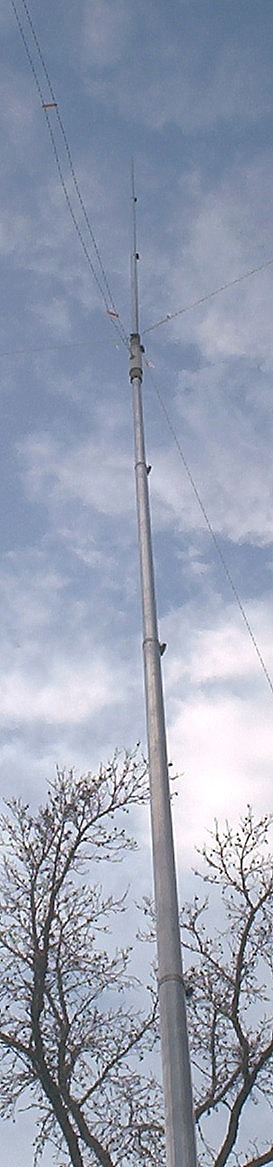
Physical Design
The use of 7 six-foot sections of 0.058 slip-fit aluminum tubing will allow easy adjustment of the feedpoint (and overall length) by varying the overlap of tubing sections. Tube ends will be slotted and clamped with SS hose clamps (not drilled).
The feedpoint insulator will be 2 feet of 1-inch Schedule 40 PVC, which will be heated and formed to slip-fit outside of sections 4 (1.125″) and 5 (1″). This has an ID 1.049. The lower half of the insulator will be heated and forced over section 4; the upper half heated and swaged down to section 5 (apply 2 hose clamps while pliable). The center of the insulator will be slotted 3/8 x 2 inches with a router to provide feedline connection. A sleeve of 1¼-inch schedule 40 (ID 1.380) will then be slotted, heated, and slipped over the termination point to add strength.
The base insulator should be 10 feet of 1½-inch schedule 80 PVC pipe, which has an ID of 1.500 inches. The base of the antenna should be raised at least 8 feet to prevent RF burns. If schedule 80 is not available, schedule 40 may be used by heating and swaging down with hose clamps. However, raising the antenna without breaking schedule 40 may be tricky.
The antenna will be guyed with 3 lines of #36 nylon mason’s line. These will attach just above the center insulator and slope outward at a reasonable angle to trees or driven stakes. For hurricane duty, the guys should be ¼-inch nylon, tied to driven 1-inch (by 48″) galvanized steel pipe stakes. One guy line must be opposed to the feed line so that it may be pulled taut. The feedline should run horizontal for 40 feet or more.
Data and Materials Tables
Table 1: Texas Towers Aluminum
from http://www.texastowers.com/aluminum.htm
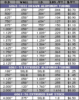
| Table 2: Aluminum Materials: 6063-T832 in 6-foot sections | ||||
|---|---|---|---|---|
| Sec. | Size | /ft | #Ft. | Cost |
| 8 | 0.625 | 0.90 | 6 | 5.40 |
| 7 | 0.750 | 1.00 | 6 | 6.00 |
| 6 | 0.875 | 1.10 | 6 | 6.60 |
| 5 | 1.000 | 1.20 | 6 | 7.20 |
| 4 | 1.125 | 1.35 | 6 | 8.10 |
| 3 | 1.250 | 1.55 | 6 | 9.30 |
| 2 | 1.375 | 1.75 | 6 | 10.50 |
| 1 | 1.500 | 1.95 | 6 | 11.70 |
| Base Total | $64.80 | |||
| Delivered + Texas Tax | $87.09 | |||
Notes: Section 8 not used in this project. Sections 1-4 are the lower element; sections 5-7 are the upper element. May be made with only six sections but lower element will not be as strong.
| Table 3: Other Materials | |||||
|---|---|---|---|---|---|
| Description | OD | ID | /ft | Quant. | Cost |
| 1½″ Sch-80 PVC Base Insulator www.usplastic.com |
1.900 | 1.500 | 1.27 | 10′ | 12.70 |
| 1″ Sch 40 Center Insulator | 1.315 | 1.049 | 2′ | ||
| 1¼″ Sch-40 Reinforc. Sleeve | 1.660 | 1.380 | 1½′ | ||
| 2″ SS Worm Gear Hose Clamp | 2 | ||||
| 1¾″ SS Worm Gear Hose Clamp | 2 | ||||
| 1½″ SS Worm Gear Hose Clamp | 4 | ||||
| 1¼″ SS Worm Gear Hose Clamp | 4 | ||||
| 1″ SS Worm Gear Hose Clamp | 4 | ||||
| Misc sheet metal screws | 2 | ||||
| 1¼″ homemade ladder line, #14 AWG | 40-80′ | ||||
| Ring Lugs, #8 hole | 2 | ||||
| Silicone spray can | 1 | ||||
| Aluminum anti-corrosive (Penetrox) | 1 | ||||
Overall Cost
This antenna may be constructed for about $100.
Construction Notes
The lower element uses 4 sections, overlapped about 29 inches, for strength. The upper element uses 3 sections, overlapped about 6½ inches, for low weight. Sections are slotted and clamped with worm gear hose clamps. Use Penetrox at every joint and at the feedline connection.
| Table 4: Assembly Dimensions (approximate, initial calculated) | ||||||||
|---|---|---|---|---|---|---|---|---|
| Design | Freq | EL In | EL Const | EU In | EU Const | LOA ft or in | LOA Const | OCF % (+ = up) |
| 20-meter OCF Sleeve Dipole, monobander with coax feed | 14.175 | 235″ | +34″ | 167″ | -34″ | 33.5′ 402″ | 474.8 5697.6 | +8.5% (of loa) |
| 20-10 Multiband CF Doublet with 450-ohm ladder line | 14-29 | 201″ | +0″ | 201″ | -0″ | 33.5′ 402″ | 474.8 5698 | 0% |
| 40-Meter ¼-wave Vertical | 7.150 | 33.2′ 398.4″ | 237.4 2848.8 | — | ||||
| 60-Meter ¼-wave Vertical | 5.3665 | 44.23′ 530.8″ | 237.4 2848.8 | — | ||||
Analysis
MMANA optimization shows a constant of 474 (not 468) using 14.175 MHz and actual section radii.
For multiband use, MMANA shows the best feedline to be 450-ohm ladder, side-fed, which will produce a wide SWR curve from 14 to 29 MHz, between 5:1 and 3:1, respectively. Ladderline will handle 5:1 SWR easily with no appreciable loss. Fed in this manner, the gain will be about 1.0 at 14, rising to 4.3 dbi at 29 MHz. Will be even higher on 50 and 144 (up to 7 dbi gain, but at 45 degrees).
Elevation angles: 2 and 6: 45 degrees; 10: 12 degrees; 15: 15 degrees; 17:16 degrees; and 20: 18 degrees.
Conclusion: The 20-meter vertical dipole, center-fed with 450-ohm ladder, will be a good-performing and inexpensive 20- through 10-meter omni-directional antenna, used with a tuner and current balun at the tuner. Also useable on 6 and 2, but high radiation angle will limit performance. The line should run horizontal for 40 feet or more.
Constructed as an off-center-fed sleeve dipole, coax will run up to the feedpoint inside the lower element. Since the coax will interact with the lower element, the feedpoint must be moved off-center to locate the lowest SWR. Exact measurements are yet to be determined, but a 2-meter version has a flat SWR (50 ohm) when offest 8.5 percent of overall length (see also my 2-meter sleeve dipole article).
Results
Tests based on S-meter readings on an Icom IC-706MkIIG. Gain figures are db compared to my 160-meter horizontal dipole. Each antenna was matched with the tuner (MFJ 949E). A variety of signals were measured on each band, and averaged.
| Table 5: On-air Results | ||
|---|---|---|
| Band | Gain | Note |
| 40 | Considerably less | As expected |
| 30 | About the same | As expected |
| 20 | +6 | |
| 17 | +9 to 12 | |
| 15 | +6 to 9 | Much quieter |
| 12 | +6 | |
| 10 | +12 to 18 | |
The location contains many large trees within 20 to 30 feet, and two metal structures within 30 feet. Placement in an open area would undoubtedly provide better results.
The ½-wave vertical dipole brings in a great many signals that cannot be heard on the big horizontal dipole, and is considered a complete success. Like L.B. says in his article, if you can buy a better antenna, by all means do so, but if you need an inexpensive, unobtrusive vertical, this one will do fine.
Note: Also available as a PDF: VerticalAntenna.pdf - better for printing.
73, —KV5R
How much power can the antenna system run?
As much as it would take to burn up your feed-line, or 1 inch aluminum tubing… 🙂
With a good feed-line, it should easily handle 1500 watts. It’s just a dipole, without any coils or matching devices to burn up.
73, –kv5r
I’m planning to try the 12m fiberglass pole wire vertical (two-leg dipole). It seems like the best compromise for me. Instructions are here:
http://www.dj0ip.de/app/download/5797957349/Simple+Multi-Band+Vertical+Dipole.pdf
I have an oppressive homeowner’s commune (uh, I mean association). Basically I’ll be putting this thing up when I want to operate and taking it down when I’m done – I suspect that if I’m operating at night it’s possible it will never even be noticed. I don’t really expect the neighbors to care as long as I don’t leave it up full-time, and the association vulture (uh, I mean inspector) that drives around looking for violators probably comes around only during the day.
That’s an interesting design! I have noticed that a couple places on-line are selling telescoping fiberglass poles for ~$175-$275 (depending on height). You could guy the top with crossed 80 & 40 meter inverted vees (on coax), and also run a 20 meter vertical down the pole (on ladder-line) and have 80-10, in a form that’s easily retractable.
73, –kv5r
Interesting information you have shared here. It worked just as you said it would. Thanks for showing the way.
Just popped in for an update–as I mentioned in an earlier post, I cut the PVC base pipe in half to make it less wobbly and easier to install by myself. The piece of leftover PVC had one flared end, made to fit over another piece.
A few weeks ago I noticed the unused half of the conduit lying in the garage and started thinking…soon I got out the torch and stepladder and inserted it between the bottom of the dipole and the original piece of buried PVC, raising the bottom of the antenna from 1 foot AGL to 6. The flared end of the PVC slipped right over the stub sticking out of the ground. Since the dipole was already vertical and guyed, this wasn’t too bad of a job for one person. It’s already survived a couple of thunderstorms with 30-40mph wind gusts.
Hello Harold–Now that the antenna is a few years old, are there Any improvements or modifications you can suggest before I start ordering the parts?
73
Just put it up this weekend and it seems to work as advertised.
A couple of construction notes from my experience.
1) When putting on the PVC center insulator, install the bottom element first. It’s easier to heat/stretch the PVC over the tube if you don’t have the top element already stuck into the other end.
2) using a full 10′ length of schedule 80 PVC for the base was too wobbly for me to walk up vertical by myself. I’m sure a helper or two holding the guy ropes would make it much easier. I cut it down to about 5 feet long, put half that in the ground and walked it right up.
That’s just like I did, in both cases. I put the larger tube into the heated pvc center insulator first, and I cut the sch-80 down to 5-6 feet so I could raise it. I dug a 2′ deep post-hole and sticking the end in that made it easy to walk it up.
Mine is now guyed North-South with a 75M dipole, West with string, and East with the feedline. It’s real simple and works pretty well.
Good to hear you got one working! It’s not a “great” antenna but it sure beats a quarter-waver vertical with a bunch of radials.
73, –kv5r
Dear Harold ,really formidable your antenna and yor comment easy to lear THANK 73
Most of all the antenna for HF that I use are fed with ladder line 450 ohm.
The best antenna I have built was a 40m elevated ground plane. Performance was better that I expected!!! Even worked on 80m and 160m at reduced power.
I am sure going to build this 20m vertical dipole.
Forgot to add it worked on 10m-40m at full 100 watts. 80m and 160m reduced power. Not a bad antenna.
Dear Harold,
Based on your idea, I built a wire vertical doublet on a 12m fiberglass telescopic mast, 600-Ω fed, 4:1 current balun (Balun Designs 4124 model), 2 meters of low loss coaxial, to my Elecraft K3. Very interesting results. DX is easy to perform even on qrp. When reduced space and no possibility to dispatch a good ground counterpoise this is the antenna of choice. Thank you. Bst 73’s. Philippe, F5LTB (A65BI 2009-2012, 9Q1TB 2003-2008)
I always wanted to do that but only fiberglass poles I could locate were lineman’s switch poles, very expensive like $500.
Yes, vertical 1/2 wave dipoles are always better than a 1/4-wave ground-plane, even with an excellent ground racial system. It’s because the lower element is also a radiator (doubling the signal aperture), whereas any 1/4-wave ground-plane is just simulating the missing lower element for matching purposes.
73,
–kv5r
Actually my recollection from school is that a current element over an “infinite perfect” ground plane is in *every respect* equivalent to having the image element instead of the ground plane. So the real issue here is that the quarter-wave vertical with radials is just “simulating” a true ground plane; if you really had a perfect ground plane there would be no simulating about it – it would function the same.
The other difference, though, is that the whole thing (the physical quarter wave element and its image) would be one quarter wavelength lower in height than the vertical half-wave dipole.
I theory, perhaps. But in practice, the physical aperture of an antenna determines its efficiency, all other things being equal. This is why a perfect half-wave dipole has 2.15dB gain over a perfect quarter-wave ground plane. Even if you elevate them into free space.
The “image” of a ground plane is just a mathematical explanation for a matching device, not an “active” element in any way.
73, kv5r
Dear Harold,
No more outside balun on my Vertical 2 x 5.1m doublet now. I’ve build a balanced matchbox, see on http://www.qrz.com/db/F5LTB. It tunes easily from 30 to 6m and shows a good improvement with this system. A better S/B ratio and & equally radiating power make better overall dx results.
Hpe to r u sn
73’s
Philippe, F5LTB
My current antenna is a 75m dipole and 20m vertical dipole on one coax with no balun, it works fine on all bands with autotuner.
Hi Harold,
One coax, so it means the autotuner is at, or very near to the antenna with a remote switch.
May be the next step to me is to build a switch for balanced lines like this one:
http://www.hamware.de/hardware/Switch%20ASU-502/asu502-e.htm
Bst 73’s
Philippe, F5LTB
A really good DX vertical would be an OMTA 40-20-17/15. I’ve built 5 of them, just finished a 30-17-12 meter version with really good results. Robert Wilson’s original idea was a bit more “robust” and time consuming than I wanted to bother with, so with a little bit of “cost engineering”… came up with something simpler that has netted over 4600 contacts. Really noteworthy is while the driven element (40 meter) is 1/4 wave, the other elements are 1/2 wave, producing really good receive and a little lower transmit launch angle.
BTW, the OMTAs are resonate antennas, that match well (low SWR), and make pretty nice SWL antennas for nearby bands.
Interesting website, good reading material.
73 – KJ4ADN (Silver Tip Antennas)
Hello OM,
Nice information and work you did writing on the subject of ladder line. Sir, do you know of an online 4-wire ladder line calculator?
Or, do you know of a calculator chart for 4-wire ladder Line?
Thank you for your consideration.
73,
Chuck – AA5WG
Sorry, no, I don’t know of a 4-wire ladder line calculator, or of what is 4-wire ladder line, or of why anyone would need 4 wires for ladder line. In my experience, 2 is quite enough for rf transmission.